Polymer battery encapsulation method

A battery packaging and polymer technology, which is applied in the field of polymer battery packaging, can solve the problems of battery performance impact, difficult capacity, and difficulty in meeting customers' high standards, and achieve strong market competitiveness, large capacity increase space, and product benefits. Considerable effect

Inactive Publication Date: 2009-09-16
SUNWODA ELECTRONICS
View PDF0 Cites 3 Cited by
  • Summary
  • Abstract
  • Description
  • Claims
  • Application Information

AI Technical Summary

Problems solved by technology

[0002] At present, most of the packaging of Li polymer PACK adopts double-sided steel sheet packaging process. The specific packaging process is to install batteries between the upper plastic steel shell and the lower plastic steel shell, and then weld the upper and lower plastic steel shells with ultrasonic waves. , this method of packaging polymer batteries is difficult to meet the high requirements of customers due to the limitation of PACK capacity / volume space, and the packaging process cost is relatively high, the quality is difficult to control, and relatively lacks market competitiveness. Specifically, There are the following problems. First, the packaging process is more complicated, the production efficiency is low, and the quality is difficult to control (in order to ensure the strength of the PACK, the ultrasonic process of plastic shell beer steel sheet injection molding is generally used, and the appearance quality is difficult to overcome due to structural factors such as: drawing die, texture The surface is inconsistent, peaked, deformed, etc.); the second is the high packaging cost and lack of market competitiveness (the number of molds required is large, and the mold opening cycle is long, it is difficult to meet short-term orders from customers, such as double-sided steel sheet ultrasonic packaging Need to open: three sets of metal molds, two sets of plastic molds); third, the capacity is difficult to meet the higher requirements of customers (due to the limitation of the structure, the required space is larger, the cell space is smaller, and the capacity is lower); fourth, the volume is relatively large It is more difficult to meet customer requirements (in order to meet the capacity requirements, the PACK structure requires a larger space); fifth, poor environmental adaptability, poor sealing and waterproof, poor heat dissipation, and battery performance may have a certain impact; six The structural strength is poor, and the performance of PACK may be unstable, which makes it difficult to meet the high standard requirements of customers.

Method used


Image

  • Polymer battery encapsulation method
  • Polymer battery encapsulation method

Examples


Embodiment Construction

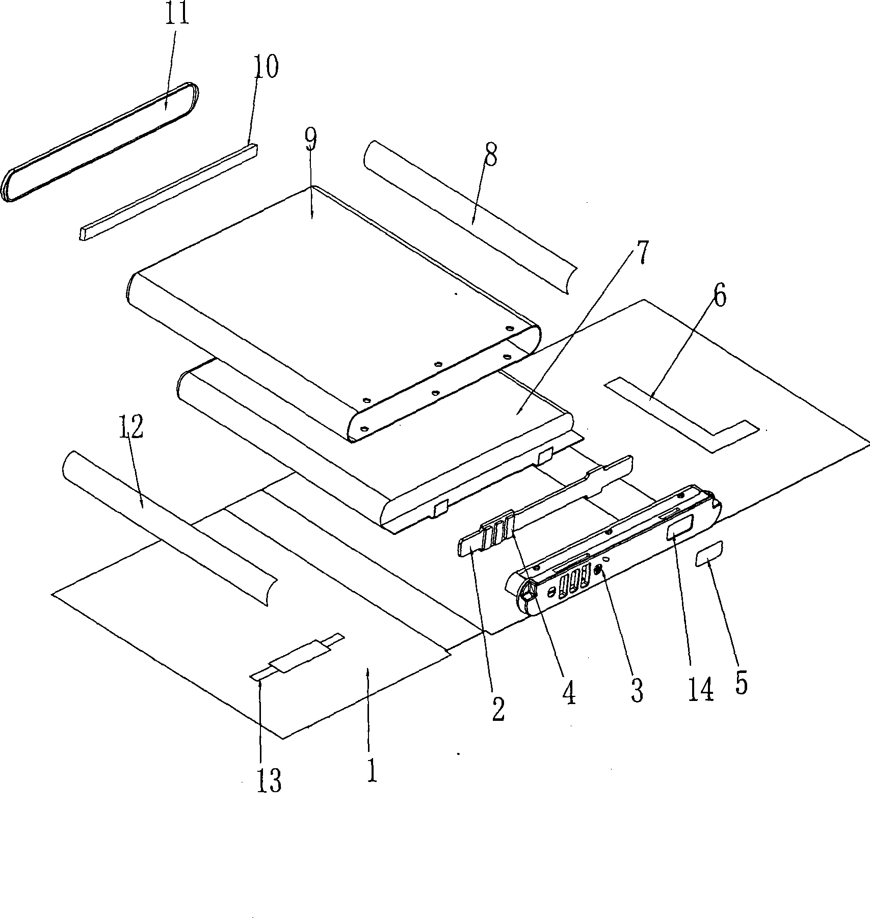
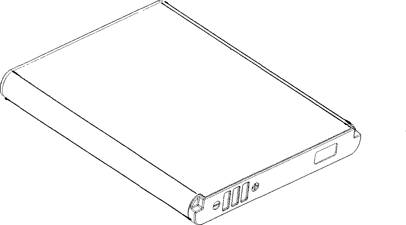
[0017] Combine below figure 1 with figure 2 , The method of the present invention will be described in detail.

[0018] A polymer battery packaging method includes the following steps:

[0019] (1) Stick EVA foam 8, 12, 10 on both sides and bottom of the battery core 7. The main function of the EVA foam 8, 12, 10 is to prevent the battery core 7 from moving in the aluminum shell 9. This step is optional. If the inner dimension of the aluminum shell 9 matches the outer dimension of the battery core 7, the EVA foam 8, 12, 10 may not be attached;

[0020] (3) Connect the PTC13 in series with the positive or negative electrode of the battery cell 7, and use the L-shaped nickel sheet 6 to connect the PTC13 with the PCM board 2. The main function of the PTC13 is to automatically disconnect when the battery temperature is too high. This step is also optional.

[0021] (4) A PCM board 2 is arranged on the upper and bottom surface of the battery core 7 to electrically connect the PCM boar...


PUM


Abstract

A polymer battery encapsulation method, including steps below: setting a PCM board on the upper bottom of a battery cell, to connect the PCM board and the battery cell electrically; clamping the PCM board on a front gluey shell; encapsulating the battery cell with the PCM board and the front glued shell into an aluminium shell; setting a bottom cover on the bottom of the aluminium shell; encapsulating the surface of the outer side of the aluminium shell with label paper. The invention is advanced with simple encapsulation, high productivity effect; the polymer battery cell is safe, secure and reliable in properties, with an appearance satisfied by the clients with high level requirements, with light weight and large upside potential of capacity, and low cost.

Description

Technical field [0001] The invention relates to a polymer battery packaging method. Background technique [0002] At present, most of the packaging of Li polymer PACK adopts the double-sided steel sheet sheathing process. The specific packaging process is to install a battery between the upper plastic steel shell and the lower plastic steel shell, and then use ultrasonic waves to weld the upper and lower plastic steel shells. This method of packaging polymer batteries is not easy to meet the high requirements of customers in this regard due to the limitation of PACK capacity / volume space, and the packaging process cost is relatively high, the quality is relatively difficult to control, and the relatively lack of market competitiveness, specifically There are the following problems. First, the packaging process is more complicated, the production efficiency is low, and the quality is difficult to control (in order to ensure the strength of PACK, the plastic shell sheathed steel sh...

Claims


Application Information

Patent Timeline
Patent Type & Authority Applications(China)
IPC IPC(8): H01M10/38H01M6/16
CPCY02E60/12Y02E60/10Y02P70/50
Inventor 王永红
Owner SUNWODA ELECTRONICS
Why Eureka
Try Eureka