
Combined die cutting roller

A die-cutting roller and combined technology, which is applied in metal processing and other directions, achieves the effects of low scrap cost, convenient disassembly, and convenient maintenance and operation

Inactive Publication Date: 2009-09-23
BROTECH GRAPHIC
View PDF0 Cites 4 Cited by
  • Summary
  • Abstract
  • Description
  • Claims
  • Application Information

AI Technical Summary

Problems solved by technology

[0004] In order to solve the existing technical problems, the present invention provides a new combined die-cutting roller that can cut complex shapes and is convenient for tool change

Method used


Image

  • Combined die cutting roller
  • Combined die cutting roller

Examples


Embodiment Construction

[0018] The present invention will be further described below in conjunction with the accompanying drawings and specific embodiments.

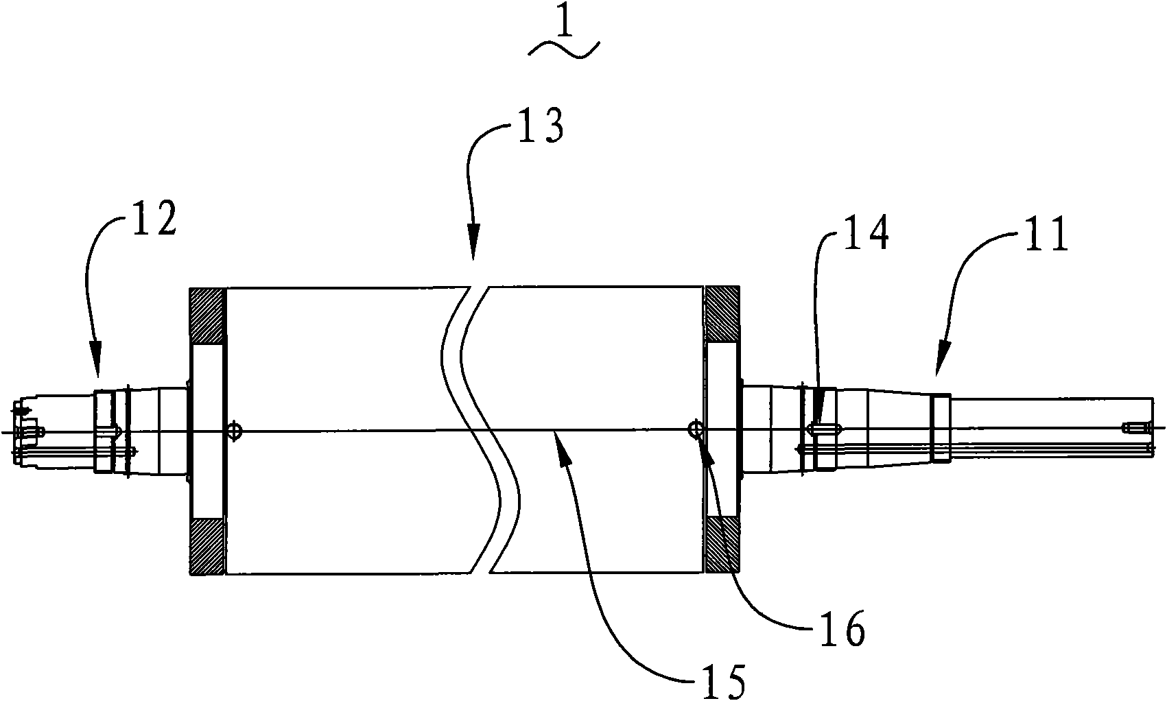
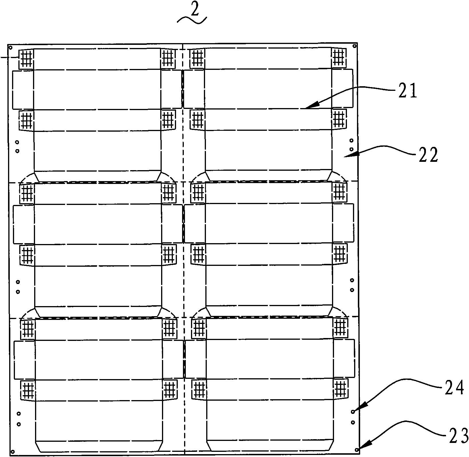
[0019] Such as figure 1 and figure 2 As shown, a combined die-cutting roller, which includes a roller entity 1 and a die-cutting part movably connected to the roller entity 1; the die-cutting part is a sheet-shaped knife skin 2 for die-cutting , The knife skin 2 is provided with a knife edge 21 with a certain shape and arrangement. According to the size of the die-cutting object and the die-cutting requirements, the roller body 1 and the knife skin 2 are selected, and the knife skin 2 must be installed on the roller body. After the die-cutting roller is installed on the die-cutting device, the die-cutting operation is carried out according to the production requirements. When the blade 21 is damaged or the blade 21 is deformed, it is possible to stop for a short time to replace or maintain the blade skin 2, but it must be stopped for a long ...


PUM


Abstract

The invention provides a combined die cutting roller which comprises a roller body and a die cutting part which is movably connected on the roller body; and the die cutting part is plate-shaped cutter housing used for die cutting. The invention has the beneficial effects that: a die cutter is made into the plate-shaped cutter housing and then stuck and arranged on the surface of a revolving body of the roller body, the replacement and maintenance operation of the cutter housing are convenient and the scrapping cost is low; in addition, intricate blades can be manufactured on the cutter housing base, thus meeting the cutting requirement in the market; and the die cutting roller has convenient installation and dismantling.

Description

【Technical field】 [0001] The invention relates to the technical field of die-cutting rollers, in particular to a combined die-cutting roller. 【Background technique】 [0002] The existing roller-type die-cutting device generally has two die-cutting rollers arranged up and down oppositely, and the material to be cut passes between the two die-cutting rollers to realize cutting. The die-cutting roller has die-cutting knives arranged on the outer peripheral surface of the roller. [0003] There are two structural forms of die-cutting rollers, integral type and combined type. Integral die-cutting roller, which directly processes the blade on the surface of the roller through special edge grinding equipment. The blade can be in a complex shape. Generally, multiple groups of blades are evenly distributed along the surface of the roller, but this thin and sharp blade It is very easy to wear and tear. After a period of use, it is necessary to grind and maintain the die-cutting knif...

Claims


Application Information

Patent Timeline
IPC IPC(8): B26D1/26B26D7/26
Inventor 李新
Owner BROTECH GRAPHIC
Learn More