
Standby management method and relevant standby management module thereof

A management module and management method technology are applied in the fields of standby management methods and related management devices and chipsets, which can solve problems such as user inconvenience and achieve the effect of increasing convenience.

Active Publication Date: 2009-09-23
VIA TECH INC
View PDF0 Cites 17 Cited by
  • Summary
  • Abstract
  • Description
  • Claims
  • Application Information

AI Technical Summary

Problems solved by technology

However, when the system is in the standby state of S1 or S3, the display unit will be turned off, and it will take a long time to return to the normal state. If the user needs to watch the screen at this time, he must manually issue a recovery command such as clicking the mouse , waiting for the system to return to the normal state from the standby state, which will cause inconvenience to the user

Method used


Image

  • Standby management method and relevant standby management module thereof
  • Standby management method and relevant standby management module thereof
  • Standby management method and relevant standby management module thereof

Examples


Embodiment Construction

[0012] In order to make the above and other objects, features and advantages of the present invention more comprehensible, preferred embodiments are listed below and described in detail in conjunction with the accompanying drawings.

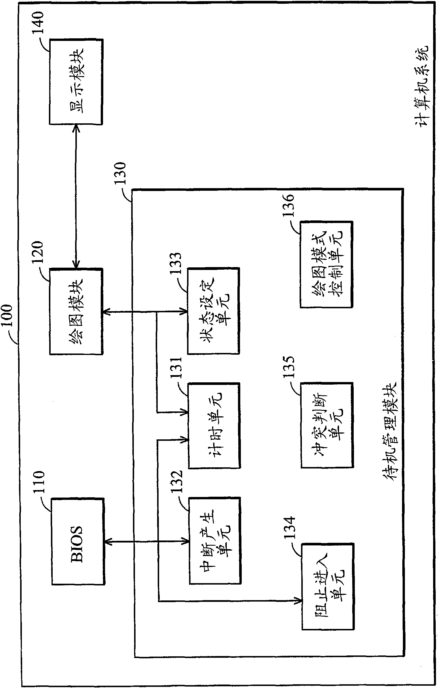
[0013] figure 1 A computer system 100 is shown in accordance with an embodiment of the present invention. Wherein, the computer system 100 can be operated in a working state (such as the S0 state of the ACPI standard) and multiple standby states (such as the S1 or S3 state of the ACPI standard), and only when operating in the working state, the computer system 100 is in normal operation state, and the rest of the standby states are dormant states. Such as figure 1 As shown, the computer system 100 at least includes a basic input output system (hereinafter referred to as BIOS) 110 , a graphics module 120 , a standby management module 130 and a display module 140 . The BIOS 110 is used to set the state of the computer system, such as a working s...


PUM


Abstract

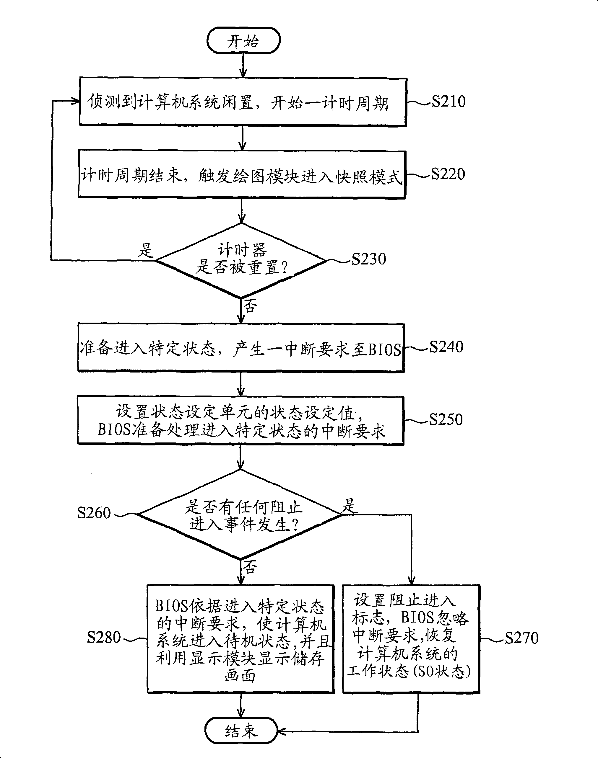
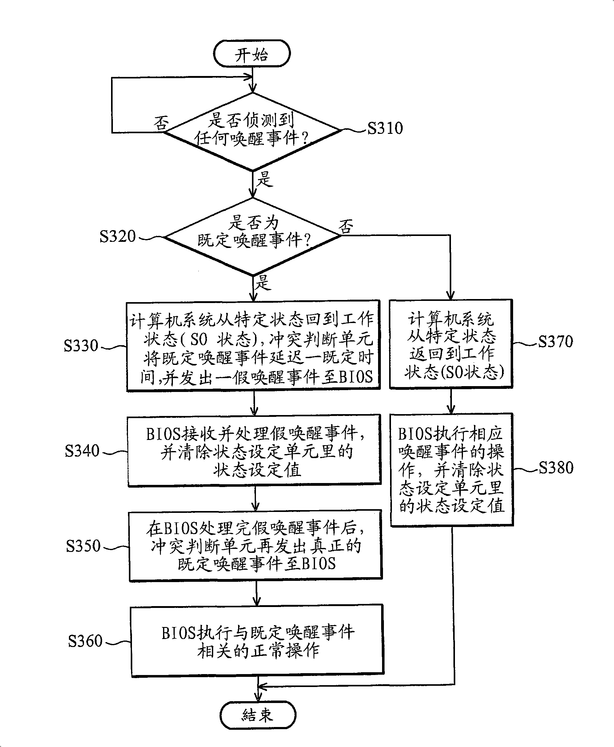
The invention provides a standby management method and a relevant standby management module thereof, wherein the standby management module is applied to a computer system. The computer system comprises a basic input and output system, a drawing module and a display module, and can be operated in a working state and at least one standby state. The standby management module comprises a timing unit and an interrupt generating unit. The timing unit is used for starting a timing cycle when a computer system is leaved unused by detection. The interrupt generating unit is used for generating an interrupt request to the basic input and output system so as to require preparing for entering a specific state when the timing cycle is over. When the interrupt generating unit is in the specific state, the computer system enters the standby state, and then a phase-locked loop circuit which the display module corresponds to is opened, the phase-locked loop circuits which the other units corresponds to are closed, and the drawing module obtains a storage picture by a fixing region of a storage unit and displays the storage picture in the display module.

Description

technical field [0001] The present invention relates to a standby management method and its related management device and chipset, in particular to a standby management method based on the S1 or S3 state of the Advanced Configuration and Power Interface (ACPI) and its related management device and chipset. Background technique [0002] For the purpose of power saving, general computer systems, especially portable computers such as notebook computers, adopt the Advanced Configuration and Power Interface (ACPI) standard to manage their power supply. ACPI defines five states, for example: S0, S1, S3, S4, and S5. The computer system generally works in the normal state (S0 state), and when the computer system is idle for a period of time, it will enter the relatively power-saving standby state S1 to S5, wherein S3 saves power more than S1, S4 saves power than S3, and so on. [0003] A basic input / output system (basic input / output system, hereinafter referred to as BIOS) in a cu...

Claims


Application Information

Patent Timeline
IPC IPC(8): G06F1/32G06F9/445
CPCG09G2330/022G06F1/3203
Inventor 秦双双黄正维
Owner VIA TECH INC
Learn More