Unlock instant, AI-driven research and patent intelligence for your innovation.

Kinescope of cathode ray tube

A cathode ray tube and cathode technology, which is applied in the field of cathode ray tube picture tubes, can solve problems such as poor image effect, increased circuit cost, and cumbersomeness, and achieve the effect of reliable functional indicators and low cost

Inactive Publication Date: 2009-09-23
KONKA GROUP
View PDF0 Cites 0 Cited by
  • Summary
  • Abstract
  • Description
  • Claims
  • Application Information

AI Technical Summary

Problems solved by technology

[0004] But the shortcoming of above-mentioned method is that line scanning circuit is more complicated than original circuit, and the processing of image signal is extremely complicated at the same time, loaded down with trivial details, and circuit cost increases a lot; , and then change the digital signal into an analog signal, etc., which will inevitably result in poor image quality

Method used


Image

  • Kinescope of cathode ray tube
  • Kinescope of cathode ray tube

Examples


Embodiment Construction

[0017] Preferred embodiments of the present invention will be specifically described below in conjunction with the accompanying drawings, wherein the accompanying drawings constitute a part of the application and are used together with the embodiments of the present invention to explain the principles of the present invention. For the sake of clarity and simplicity, detailed descriptions of known functions and constructions in the devices described herein will be omitted when it may obscure the subject matter of the present invention.

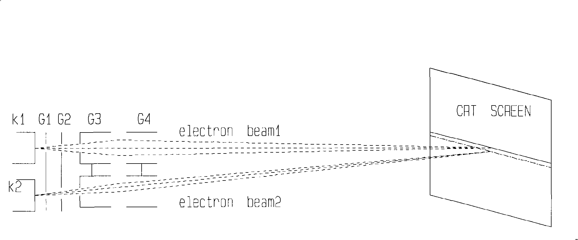
[0018] Such as figure 1 as shown, figure 1 It is a structural schematic diagram of the CRT picture tube described in the embodiment of the present invention, at least including: a glass vacuum tube and two groups of electron guns-the first group of electron guns and the second group of electron guns packaged in the diameter of the glass vacuum tube. The two groups of electron guns are identical in structure, only two The group of electron guns...


PUM


Abstract

The invention discloses a kinescope of a cathode ray tube, which is characterized by at least comprising a glass vacuum tube and two groups of electron guns packaged in the glass vacuum tube, wherein the cathodes of the first group of electron guns and the cathodes of the second group of electron guns are independent respectively, and a first grid, a second grid, a third grid and a fourth grid are shared by the first group of electron guns and the second group of electron guns; the first group of electron guns and the second group of electron guns form a predetermined angle, and the cathodes thereof are driven by a driving circuit and then emit two groups of electron beams hitting on two adjacent lines on a cathode ray tube screen; the kinescope of the cathode ray tube solves the interline flicker problem of interlaced scanning televisions in the prior art, the scanning effects thereof are the same as progressive scanning televisions while the image effect is far better than the existing progressive scanning televisions, little cost is increased on the basis of the original circuit, and the functional indexes are reliable, convenient, simple and practical.

Description

technical field [0001] The invention relates to the field of television and other displays, in particular to a cathode ray tube picture tube. Background technique [0002] At present, the common TV system standard is interlaced scanning, and its defect is that there is flicker between lines. For example, the frame frequency of PAL system is 25Hz, which causes 25Hz flicker between adjacent lines on the screen, which makes people uncomfortable to watch. , and reduces image clarity. [0003] The existing way to solve this interlaced flicker defect is to increase the line scanning frequency and double the line scanning frequency. For example, the line frequency of the original PAL system is 15625Hz, and the line frequency after the increase is 31250Hz. The line frequency also needs to be doubled, so that the line scanning frequency can be synchronized with the image signal after the line frequency is increased. At this time, progressive scanning can be performed (of course, the...

Claims


Application Information

Patent Timeline
Patent Type & Authority Applications(China)
IPC IPC(8): G09G1/00H01J31/12
Inventor 赵邙
Owner KONKA GROUP