Novel ceiling antenna

A ceiling-mounted antenna, a new type of technology, applied in the direction of the antenna, the resonant antenna, the mid-position feed between the antenna terminals, etc., can solve the problems of low standing wave and poor stability, achieve low standing wave, improve production efficiency, and reduce costs. Effect

Inactive Publication Date: 2009-09-23
FUJIAN QUANZHOU HUAHONG COMM CO LTD
View PDF0 Cites 6 Cited by
  • Summary
  • Abstract
  • Description
  • Claims
  • Application Information

AI Technical Summary

Problems solved by technology

[0005] By adopting the aforementioned technical scheme, the beneficial effects of the present invention are: changing the radiator from the original double-sleeve vibrator to stamping, saving a lot of processes on the original basis, greatly improving production efficiency and reducing costs, improving In order to solve the disadvantages of difficult debugging, poor stability and directivity, the prepared ceiling antenna has the advantages of wide frequency band, low VSWR and high gain, and is suitable for indoor broadband coverage requirements.

Method used


Image

  • Novel ceiling antenna
  • Novel ceiling antenna

Examples


Embodiment Construction

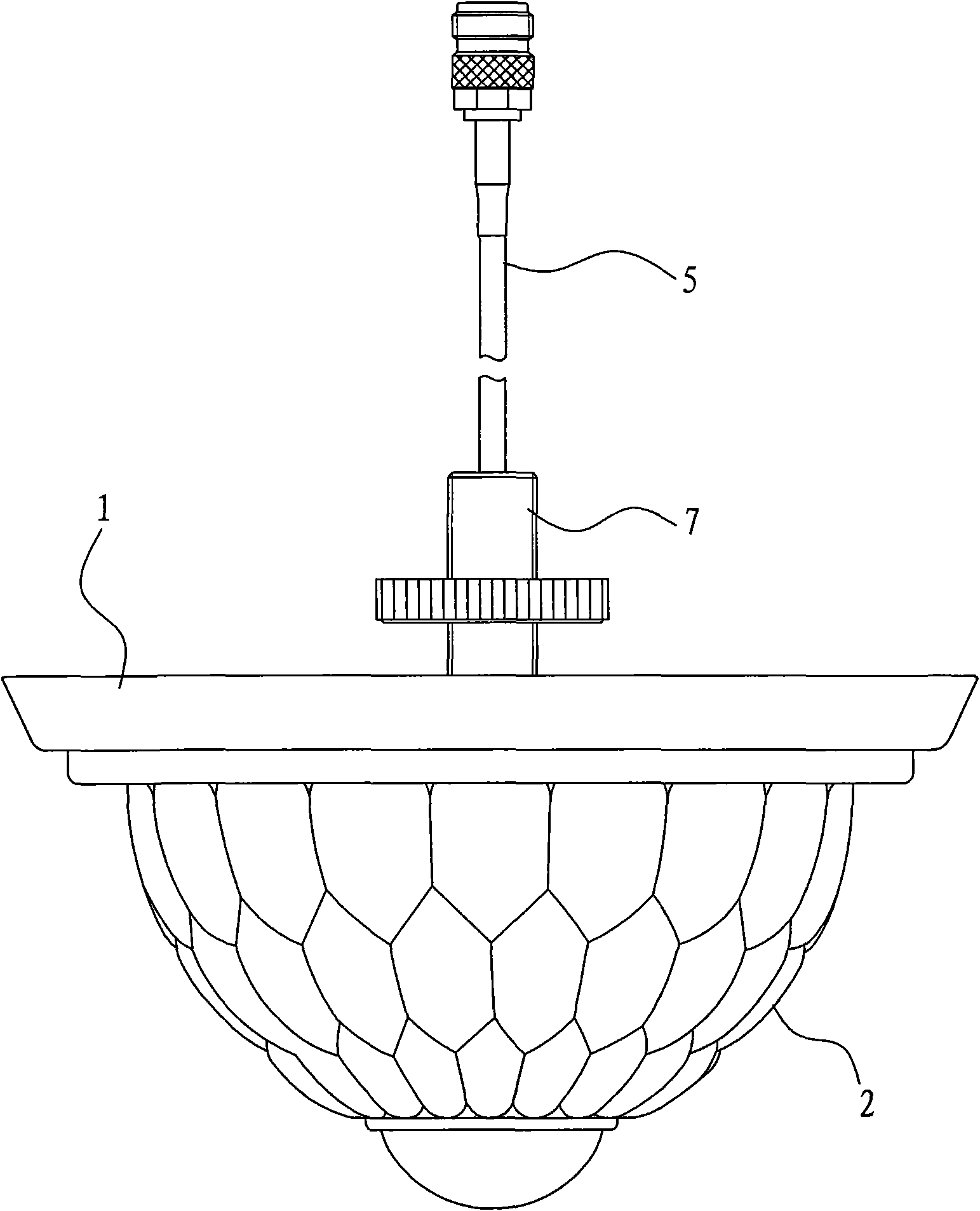
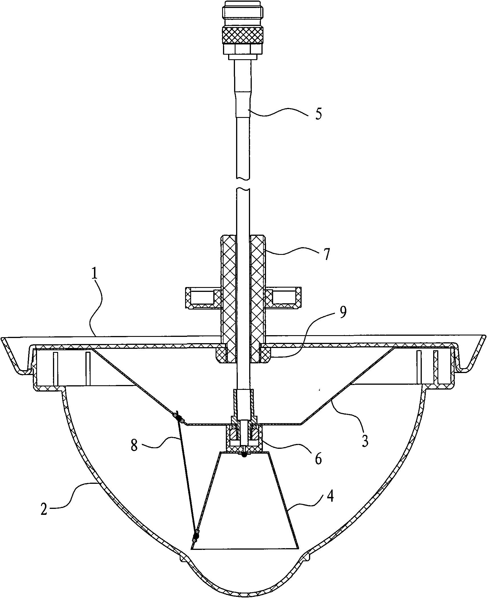
[0008] refer to figure 1 and figure 2 , the embodiment discloses a new type of ceiling antenna, which includes a cover plate 1, an outer cover 2, an upper cone vibrator 3, a lower cone vibrator 4, a coaxial cable 5, a spacer 6, a stud 7, a coupling vibrator 8 and a fixing nut 9 , wherein, one end of the stud 7 is passed through the middle of the cover plate 1, and the fixing nut 9 is screwed on the end of the stud 7 on the bottom surface of the cover plate 1, so that when the other end of the stud 7 is fixed to the ceiling, the cover The board 1, the cover 2 on it, the radiator, etc. are suspended on the ceiling, and the stud 7 is an axial hollow structure, through which the coaxial cable penetrates into the bottom of the cover board 1 and connects with the radiator. The radiator is arranged under the cover plate 1, and the outer cover 2 is arranged under the cover plate 1 and contains the radiator inside. The radiator includes an upper cone vibrator 3, a lower cone vibrator...


PUM


Abstract

The invention provides a novel ceiling antenna with low cost and convenient debugging process, comprising a cover plate, a shell and a radiator, wherein the radiator is arranged below the cover plate; the shell is arranged below the cover plate and contains the radiator therein; the radiator comprises an upper conical vibrator, a lower conical vibrator, a spacer, a coaxial cable and a coupling vibrator; the upper conical vibrator is a hollow structure die-stamped by aluminium alloy; the top of the upper conical vibrator is provided with a spreading part which extends horizontally; the upper conical vibrator is inverted and arranged below the cover plate by the spreading part; the lower conical vibrator is a hollow structure die-stamped by the aluminium alloy; the top of the lower conical vibrator and the bottom of the upper conical vibrator are arranged intermittently at the distance of 3-15mm by the spacer; the external conductor and the internal conductor of the coaxial cable are connected with the upper conical vibrator and the lower conical vibrator respectively; and the coupling vibrator is arranged between the external side wall of the upper conical vibrator and the external side wall of the lower conical vibrator.

Description

technical field [0001] The invention relates to an antenna, in particular to a novel ceiling-absorbing antenna for CDMA, GSM, DCS, PHS, 3G and WLAN frequency bands. Background technique [0002] The antenna is an indispensable key component in the electronic field of modern society, and its performance is directly related to whether the work efficiency of transmitting and receiving signals can be fully utilized. The structure of the current ceiling antenna is a combination of double aluminum alloy sleeves and several coupling vibrators, which is characterized by high cost, poor consistency, low production efficiency and instability of debugging, and the radiation has a certain direction sex. Contents of the invention [0003] The purpose of the present invention is to provide a new type ceiling antenna with low cost and convenient debugging. [0004] The technical solution adopted in the present invention is as follows: a new ceiling antenna, including a cover plate, an ...

Claims


Application Information

Patent Timeline
Patent Type & Authority Applications(China)
IPC IPC(8): H01Q1/36H01Q9/28H01Q13/08
Inventor 詹镇安陈仁纯
Owner FUJIAN QUANZHOU HUAHONG COMM CO LTD
Why Eureka
Try Eureka