Three-channel integrated short-wave receiving antenna

A short-wave receiving, three-channel technology, applied in the direction of antenna, loop antenna, antenna grounding device, etc., can solve the problems of inapplicability, large space, etc., and achieve the effect of strong signal receiving ability, small coupling effect and good transmission characteristics

Inactive Publication Date: 2011-11-23
国营第三八八厂
View PDF6 Cites 4 Cited by
  • Summary
  • Abstract
  • Description
  • Claims
  • Application Information

AI Technical Summary

Problems solved by technology

The utility model patent with the notification number CN 201060945 discloses a short-wave inverted V-shaped end-loaded broadband antenna, which includes four antenna oscillator wires and an antenna mast. The four antenna oscillator wires are paired in pairs to form two pairs of dipole antennas. The vibrator, the two dual vibrators are symmetrical, the two antenna vibrator wire feed ends of each dual vibrator are connected in parallel and then connected to the impedance converter, the ends are diverged and each passes through a network matcher grounding grid, and the input end of the impedance converter is connected to the RF feeder; The ends of the four antenna vibrator wires can be fixed on the four corners of a rectangle on the ground to form an inverted V shape; but the space occupied by the above-mentioned short-wave antenna array is still too large to be suitable for vehicle-mounted and portable devices, and cannot be installed in a few places. Excellent reception performance and channel count in a small footprint

Method used


Image

  • Three-channel integrated short-wave receiving antenna
  • Three-channel integrated short-wave receiving antenna
  • Three-channel integrated short-wave receiving antenna

Examples


Embodiment Construction

[0013] The present invention will be further described below in conjunction with the accompanying drawings.

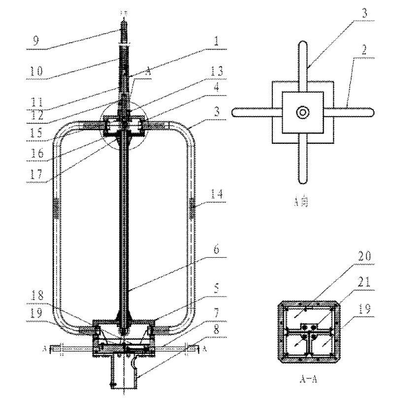
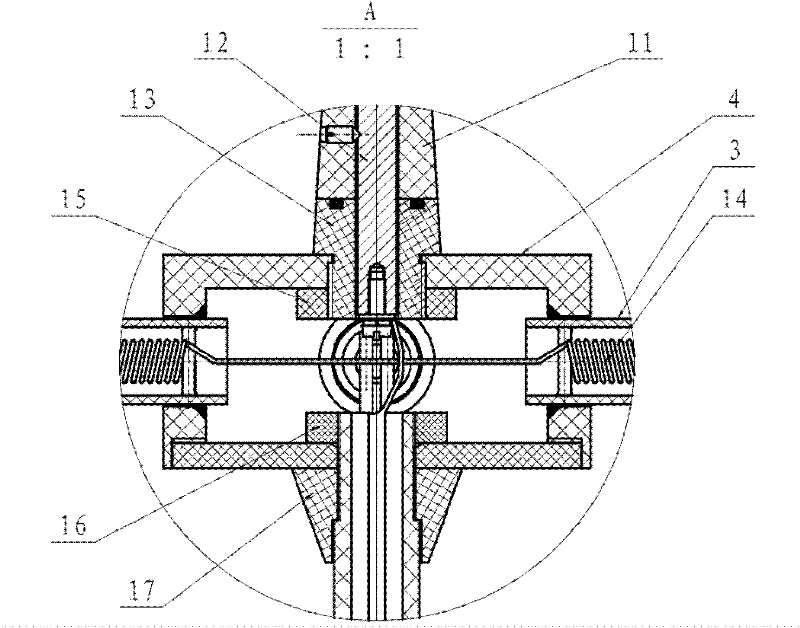
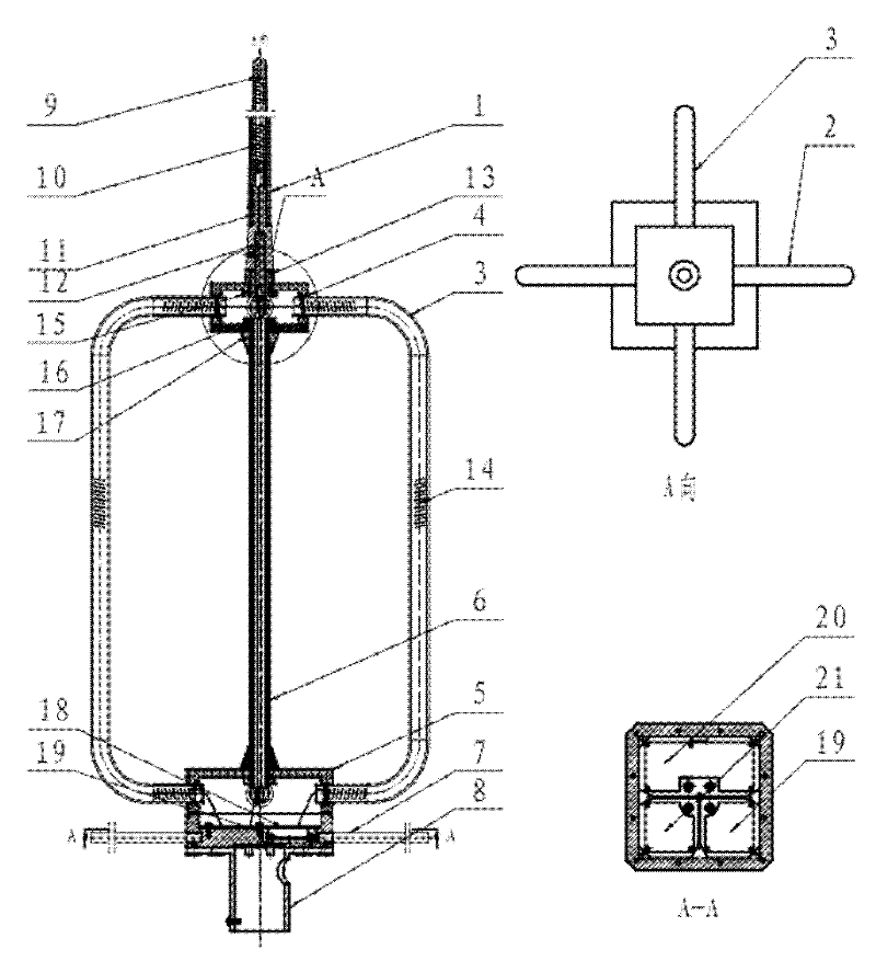
[0014] The invention includes a whip antenna, a first loop antenna, a second loop antenna, an upper cavity, a lower cavity, a base and a ground net; the whip antenna contains a whip antenna core, and the whip antenna core is welded to the connecting metal seat at the bottom Together, connect the metal seat and the socket core to be threaded, and then pass a wire through the threading tube, and connect it to the input end of the whip antenna amplifier in the lower cavity, and the output end of the whip antenna amplifier is connected to the RF connector through the wire; There is a loop antenna core inside the first loop antenna, and the loop antenna core is connected to the input end of the first loop antenna amplifier through a lead-out line; there is a loop antenna core inside the second loop antenna, and the loop antenna core is connected to the second loop antenna th...


PUM


Abstract

The invention provides a three-channel integrated short-wave receiving antenna, belonging to the field of receiving short-wave frequency band signals and comprising a whip antenna, a first loop antenna, a second loop antenna, an upper cavity, a lower cavity, a base and an earth screen, wherein the whip antenna is internally provided with a whip antenna core which is welded with a connecting metal base at the lower part; the connecting metal base is in threaded connection with a socket core and connected with an input end of a whip antenna amplifier through the lower cavity; an output end of the whip antenna amplifier is connected with an RF (radio frequency) connector by a guide line; the first loop antenna is internally provided with a loop antenna core which is connected to an input end of a first loop antenna amplifier by an outgoing line; the second loop antenna is internally provided with a loop antenna core which is connected with an input end of the second loop antenna amplifier by an outgoing line; and the second loop antenna is fixed with the first loop antenna crosswise by the upper cavity and the lower cavity. The three-channel integrated short-wave receiving antenna is suitable for vehicle-mounted and portable equipment and reaches preferable receptivity and channel number in the smaller space.

Description

technical field [0001] The invention belongs to the field of receiving short-wave frequency band signals, and in particular relates to a miniaturized three-channel integrated short-wave radar receiving antenna technology. Background technique [0002] Ordinary short-wave antennas are large in size, and the antenna array occupies a huge area. For vehicle-mounted and portable devices, small antenna size is the most basic requirement. At present, there are some relatively mature technologies for short-wave small receiving antennas, such as helical antennas and small loop antennas. [0003] For example, the utility model patent with the notification number CN201126858 discloses a relatively small-volume broadband high-gain high-power omnidirectional shortwave antenna. The antenna mainly consists of three parallel bottom-fed whip antennas 2, 3, 4 with a total height H located on a circle with a radius R. At the feeding point, a small whip antenna 15 with a height of H↓[2] is ad...

Claims


Application Information

Patent Timeline
IPC IPC(8): H01Q1/12H01Q1/36H01Q1/48H01Q7/00H01Q21/28
Inventor 陈智会罗晓斌李京萍
Owner 国营第三八八厂
Why Eureka
Try Eureka