
Pneumatic tire

A technology for pneumatic tires and tires, which is applied in the directions of pneumatic tires, reinforcement layers of pneumatic tires, and tire parts, etc., can solve problems such as decreased handling stability, and achieve the effects of suppressing performance changes, reducing cross-sectional area, and suppressing heat generation.

Active Publication Date: 2009-09-23
THE YOKOHAMA RUBBER CO LTD
View PDF3 Cites 2 Cited by
  • Summary
  • Abstract
  • Description
  • Claims
  • Application Information

AI Technical Summary

Problems solved by technology

[0005] However, the pneumatic tire having the above-mentioned structure has such a problem that, for example, when continuous running on a circular track is carried out, the steering stability is reduced due to heat generation of the tire.

Method used


Image

  • Pneumatic tire
  • Pneumatic tire
  • Pneumatic tire

Examples


Embodiment

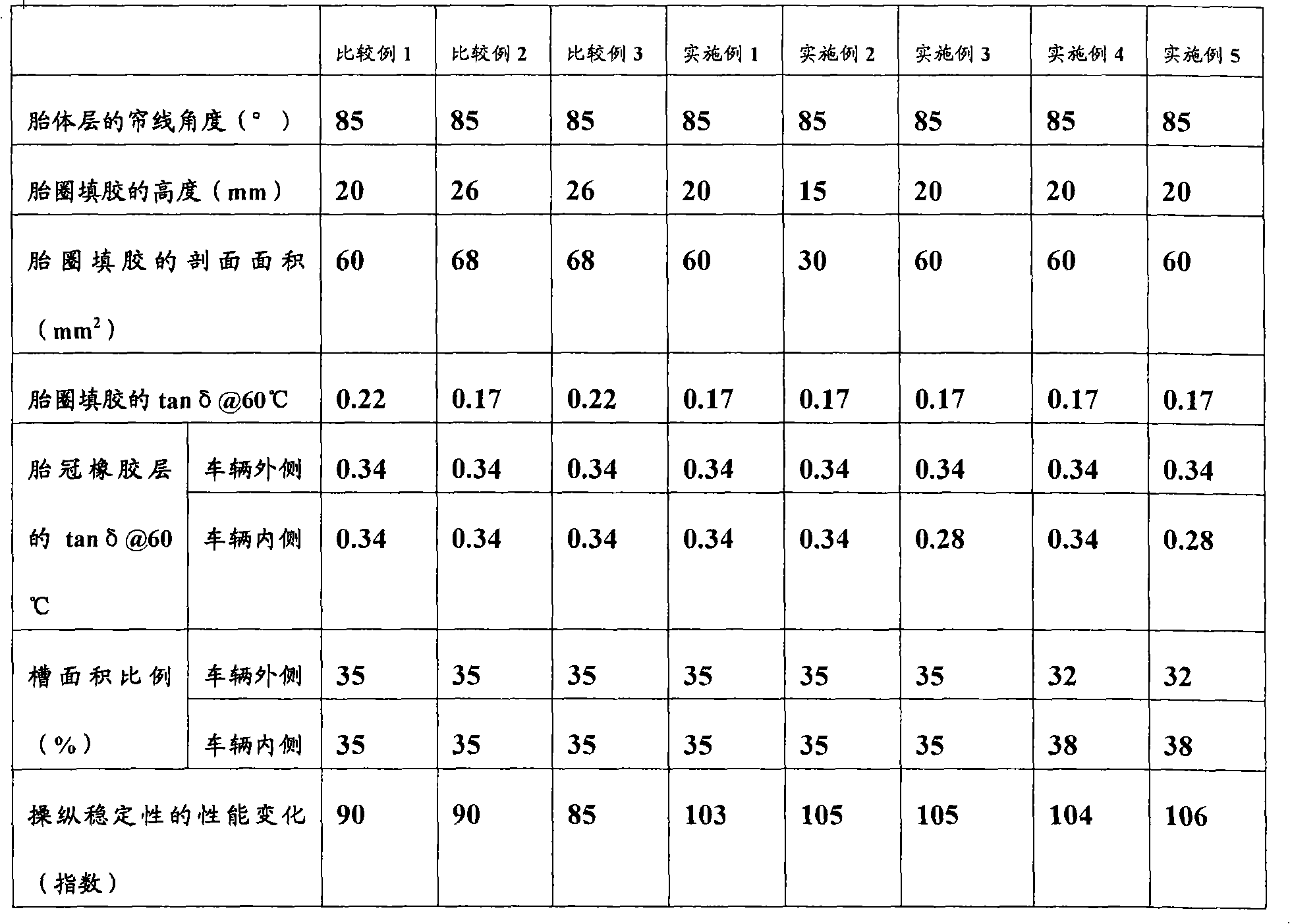
[0046] Pneumatic tires of Comparative Examples 1 to 3 and Examples 1 to 5 were produced respectively, wherein the tire size was 235 / 40R18, and the cord angle of the frame between a pair of bead parts with respect to the tire circumferential direction was set to 85° ° single-layer carcass layer, the belt layer is arranged on the outer peripheral side of the carcass layer at the tread portion, and the carcass layer is wound around the bead cores arranged in each bead portion from the inner side to the outer side of the tire. The body portion and the turnup portion of the carcass layer sandwich the bead filler placed on the bead core, and the turnup portion of the carcass layer extends to the belt so as to overlap the end portion of the belt layer. In addition, the height of the bead filler from the heel of the bead filler, the cross-sectional area of ​​the bead filler, and the tanδ at 60°C of the rubber composition constituting the bead filler are set as shown in Table 1 to const...


PUM


Abstract

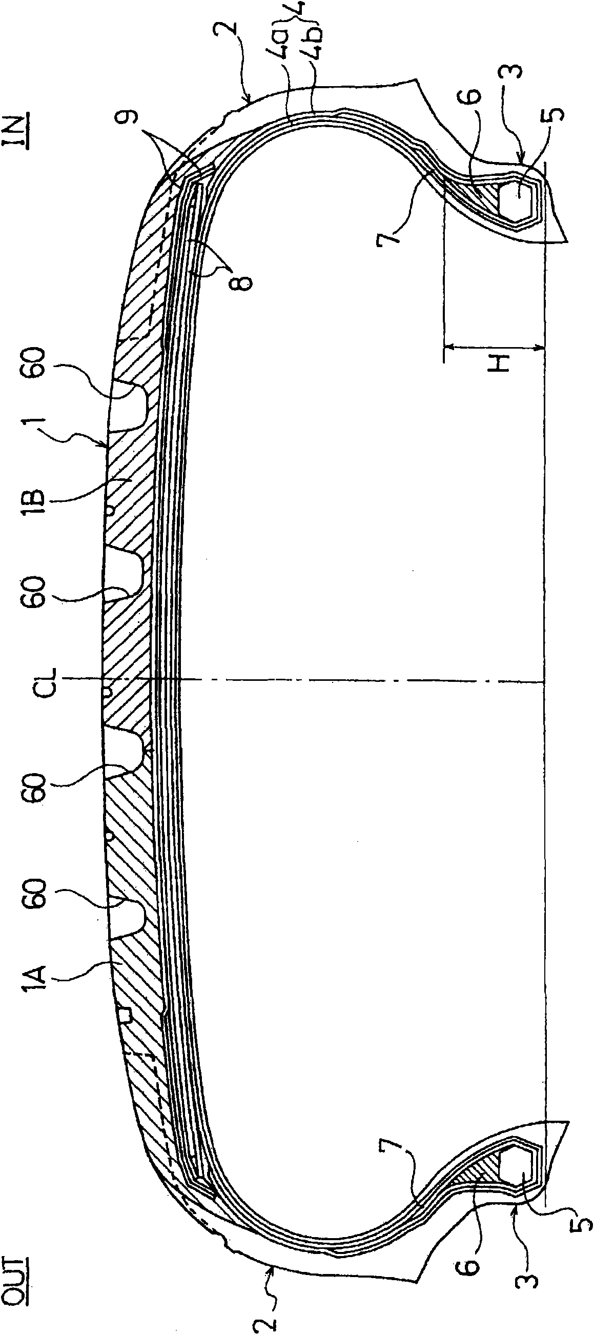
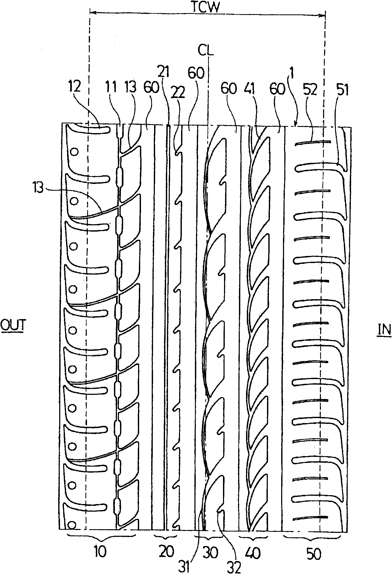
A pneumatic tire that even when having a carcass layer of one-ply structure provided with its upward wound portion extending to an inferior area of belt layer so as to overlap an edge portion of the belt layer, inhibits any deterioration of driveability performance by continuous travel. The pneumatic tire has a carcass layer of one-ply structure, the cord angle of which with respect to the circumferential direction of the tire is in the range of 75 DEG to 90 DEG , provided between a pair of bead portions. At a tread portion, the carcass layer on its outer circumferential side is provided with a belt layer. The carcass layer is wound up around the bead core disposed in each of the bead portions from the tire inside to the outside so that the bead filler disposed on the bead core is pinched by the main body portion and upward wound portion of the carcass layer. The upward wound portion of the carcass layer extends to an inferior area of the belt layer so as to overlap an edge portion of the belt layer. The feature of the pneumatic tire resides in that the height of the bead filler from bead heel is 25 mm or less, and that the sectional area of the bead filler is 65 mm2 or less, and that the rubber composition constituting the bead filler exhibits a value of tan delta at 60 DEG C of 0.20 or less.

Description

technical field [0001] The present invention relates to a pneumatic tire having a carcass layer having a single-layer structure in which a rolled-up portion extends to a region below the belt layer in such a manner as to overlap an end portion of the belt layer. Pneumatic tires with performance changes in handling stability caused by driving. Background technique [0002] In recent years, for pneumatic tires mounted on sports vehicles and other vehicles that are expected to run at high speeds, the demand for weight reduction has become increasingly strict. handling stability. [0003] In contrast, a pneumatic tire has been proposed in which a carcass layer of a single-layer structure is placed between a pair of bead portions, and a belt layer is arranged on the outer peripheral side of the carcass layer at the tread portion to surround the carcass layer. The bead core placed on each bead portion is rolled up from the inner side of the tire to the outer side, and the bead f...

Claims


Application Information

Patent Timeline
Patent Type & Authority Applications(China)
IPC IPC(8): B60C15/06B60C5/00B60C9/08B60C11/00B60C11/03B60C11/04
CPCB60C2011/0388B60C19/001B60C15/0632B60C11/00B60C2011/0025B60C15/0045B60C11/0304B60C11/033B60C15/06B60C11/0058Y10T152/10513
Inventor 大圣康次郎
Owner THE YOKOHAMA RUBBER CO LTD
Learn More