Illumination system

A lighting system and sensing system technology, applied in the field of lighting systems, can solve problems such as difficult to meet

Inactive Publication Date: 2009-09-23
KONINKLIJKE PHILIPS ELECTRONICS NV
View PDF0 Cites 8 Cited by
  • Summary
  • Abstract
  • Description
  • Claims
  • Application Information

AI Technical Summary

Problems solved by technology

The problem in this respect is that in practice, for example due to tolerances (tolerance), aging, ambient temperature, etc., the relationship between the control signal and the output light intensity may change from one lamp to another and / or changes as a function of time
In practice, it is difficult to meet all these requirements

Method used


Image

  • Illumination system
  • Illumination system
  • Illumination system

Examples


Embodiment Construction

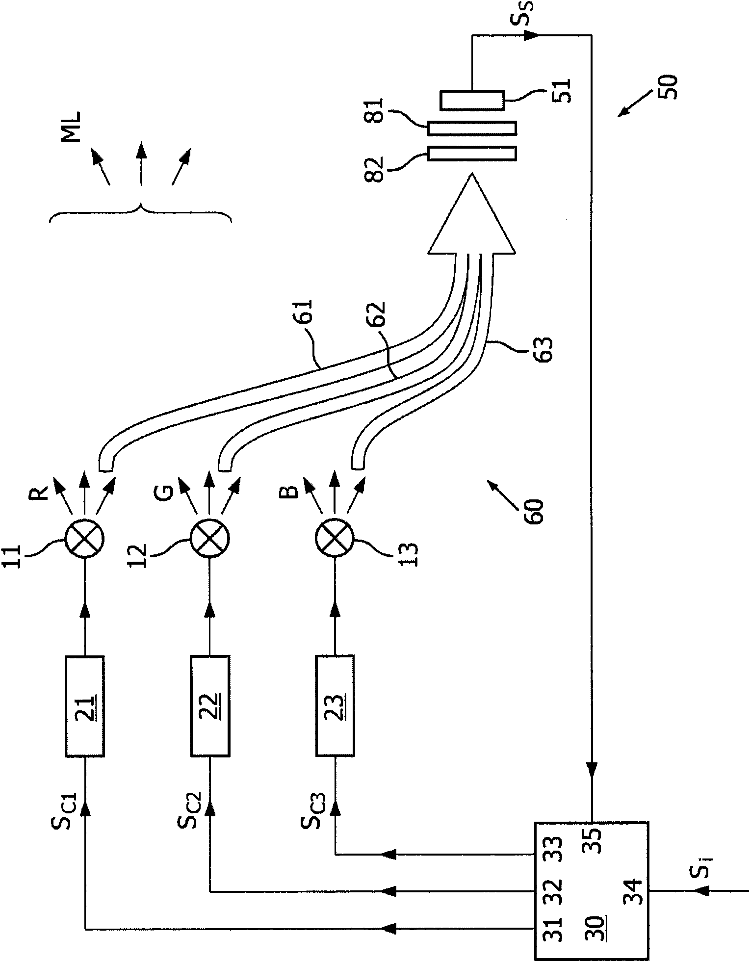
[0012] figure 1 is a block diagram schematically illustrating a lighting system 1 according to the invention. In the illustrated embodiment, the system comprises three lamps 11 , 12 , 13 with associated drivers 21 , 22 , 23 and a controller 30 with functions for generating corresponding control signals Sc1 for corresponding drivers 21 , 22 , 23 , three output terminals 31, 32, 33 of Sc2, Sc3. For example, the first lamp 11 produces red light R, the second lamp 12 produces green light G and the third lamp 13 produces blue light B. At a sufficient distance, the light outputs of the three individual lamps 11, 12, 13 are mixed and the observer observes the mixed light ML. It should be clear to those skilled in the art, and thus requires no further explanation, that the color of the mixed light as observed by a human observer depends on the relative intensities of the individual light outputs. The controller 30 has a target input 34 for receiving a target input signal Si indicat...


PUM


Abstract

An illumination system (1) comprises a plurality of lamps (11, 12, 13) for generating light (R, G, B) with mutually different colors; in an embodiment, the lamps are fluorescent lamps. A sensing system (50) comprising a color sensor (51) provides a sensor output signal (Ss) that indicates the color of the light received by the color sensor. The sensing system comprises a light guide arrangement (60) interposed between the lamps and the sensor, which is arranged in a service room (74) shielded from ambient light. Each light guide captures light from one lamp only, and the sensor receives a mixture of the captured lights. The color sensor and light guide are used in a feedback system that corrects for tolerances, lamp aging, ambient temperature etc.

Description

technical field [0001] The present invention generally relates to a lighting system for generating light comprising a plurality of light sources each producing a mutually different color and each controllable so that the respective light intensity can be varied. The system also includes a controller that generates control signals for each lamp to set the respective light intensity of each lamp. The light source may be of any suitable type, such as fluorescent lamps, LED lamps, etc.; in the following, the invention will be explained for the case of fluorescent lamps, but it should be emphasized that the invention is not limited to fluorescent lamps. In a typical embodiment, the system comprises three lamps producing red, green and blue light, respectively, so that the system is denoted as an RGB system; in the following, the invention will be explained for the case of the RGB system, but it should be emphasized Yes, the present invention is not limited to the RGB system. Bac...

Claims


Application Information

Patent Timeline
Patent Type & Authority Applications(China)
IPC IPC(8): G01J3/02G01J3/50G01J3/10F21Y101/00
CPCG02B6/2804G02B6/0068G01J3/0262G02B6/0006G01J3/50G01J3/0218H05B41/3922G01J3/51H05B33/0869G01J3/10G01J3/02H05B45/22G02B6/0001
Inventor R·P·A·德尔诺伊
Owner KONINKLIJKE PHILIPS ELECTRONICS NV
Why Eureka
Try Eureka