
Apparatus and method for determining a detector energy weighting function of a detection unit

A detection unit, energy weighting technology, applied in the field of imaging systems

Inactive Publication Date: 2009-09-23
KONINKLIJKE PHILIPS ELECTRONICS NV
View PDF0 Cites 11 Cited by
  • Summary
  • Abstract
  • Description
  • Claims
  • Application Information

AI Technical Summary

Problems solved by technology

Furthermore, statistical effects of charge detection produce energy broadening

Method used


Image

  • Apparatus and method for determining a detector energy weighting function of a detection unit
  • Apparatus and method for determining a detector energy weighting function of a detection unit
  • Apparatus and method for determining a detector energy weighting function of a detection unit

Examples


Embodiment Construction

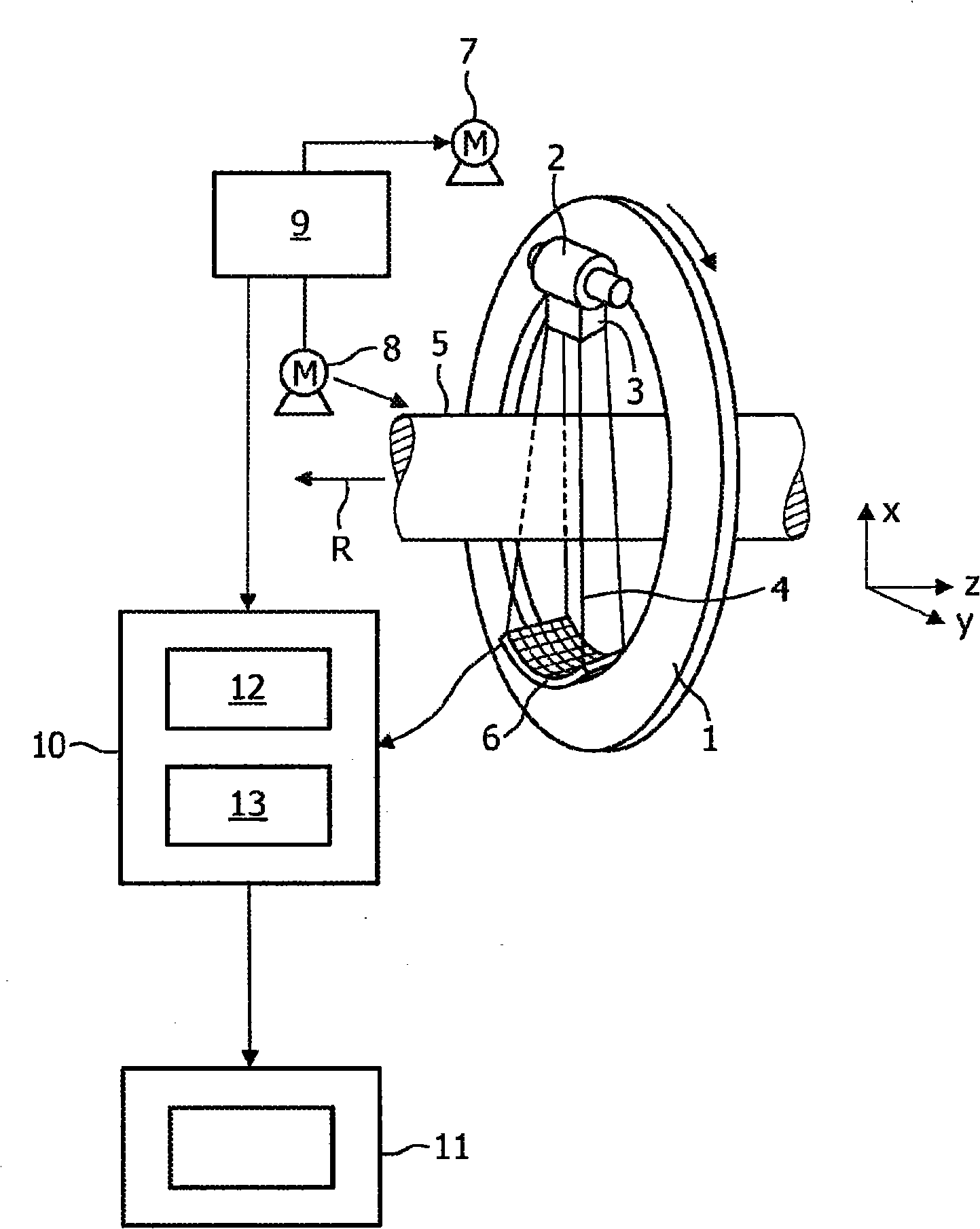
[0045] figure 1 The imaging system shown in is a spectral computed tomography system (CT system). The CT system comprises a gantry 1 which is rotatable about an axis of rotation R extending parallel to the z-direction. The polychromatic radiation source 2 is in this embodiment an X-ray tube emitting polychromatic X-ray radiation, which is mounted on the gantry 1 . The X-ray source 2 provides collimator and filter means 3 which in this embodiment form the radiation generated by the X-ray tube 2 into a conical radiation beam 4 . The radiation passes through an object (not shown), such as a patient, located in a region of interest in an examination zone 5, which in this embodiment is cylindrical. After having passed through the examination region 5, the X-ray beam 4 is incident on an energy-resolved detection unit 6, which in the present embodiment comprises a two-dimensional detection surface. The energy-resolving detection unit 6 is placed on the scanning frame 1 . The x-ra...


PUM


Abstract

The invention relates to an apparatus for determining a detector energy weighting function of a detection unit (6). The apparatus comprises a determination unit (21) for determining a spectral response function of the detection unit (6) and a calculation unit (22) for determining the detector energy weighting function by integrating the product of the spectral response function of the detection unit (6) and a given ideal detector energy weighting function.

Description

technical field [0001] The invention relates to a device and a method for determining a detector energy weighting function of a detector unit. The invention also relates to an imaging system using the determined detector energy weighting function. Background technique [0002] For example, from the article published by R.E.Alvarez and A.Macovski in Phys.Med.Biol.21 (5), 733 pages (1996), it is known that the radiation spectrum impinging on the detection unit is related to related to the detected probe signal. This relationship can be expressed, for example, as the following equation: [0003] M=c·∫de·f(E)·D(E), (1) [0004] where M represents the measured detection signal, c represents a known proportionality constant, f(E) represents the detector energy weighting function, and D(E) represents the radiation spectrum impinging on the detection unit. The measured detection signal is known, and the detector energy weighting function is usually defined as that of an ideal de...

Claims


Application Information

Patent Timeline
Patent Type & Authority Applications(China)
IPC IPC(8): G01T1/164
CPCG01T1/1647
Inventor K·J·恩格尔C·博伊默G·蔡特勒C·赫尔曼
Owner KONINKLIJKE PHILIPS ELECTRONICS NV
Learn More