
Imaging spectrometer spectral stray light correction algorithm of known target relative spectral distribution

An imaging spectrometer and spectral distribution technology, which is applied in the field of imaging spectrometer detection, can solve the problem of not being able to fundamentally eliminate the influence of stray light and reduce the level of stray light, and achieve the effect of facilitating real-time calculation, easy programming, and improving the measurement accuracy of the instrument

Active Publication Date: 2018-01-26
CHANGCHUN INST OF OPTICS FINE MECHANICS & PHYSICS CHINESE ACAD OF SCI
View PDF3 Cites 4 Cited by
  • Summary
  • Abstract
  • Description
  • Claims
  • Application Information

AI Technical Summary

Problems solved by technology

[0003] At present, the commonly used methods of eliminating stray light for imaging spectrometers are mainly to reduce the stray light of imaging spectrometers by setting stray light diaphragms, coating stray light black paint, and improving the reflectivity and transmittance of the surface of optical components in the design and processing stages. The level of astigmatism, but these measures can only reduce the level of stray light, and cannot fundamentally eliminate the impact of stray light

Method used


Image

  • Imaging spectrometer spectral stray light correction algorithm of known target relative spectral distribution
  • Imaging spectrometer spectral stray light correction algorithm of known target relative spectral distribution
  • Imaging spectrometer spectral stray light correction algorithm of known target relative spectral distribution

Examples


Embodiment Construction

[0037] The present invention will be described in further detail below in conjunction with the accompanying drawings.

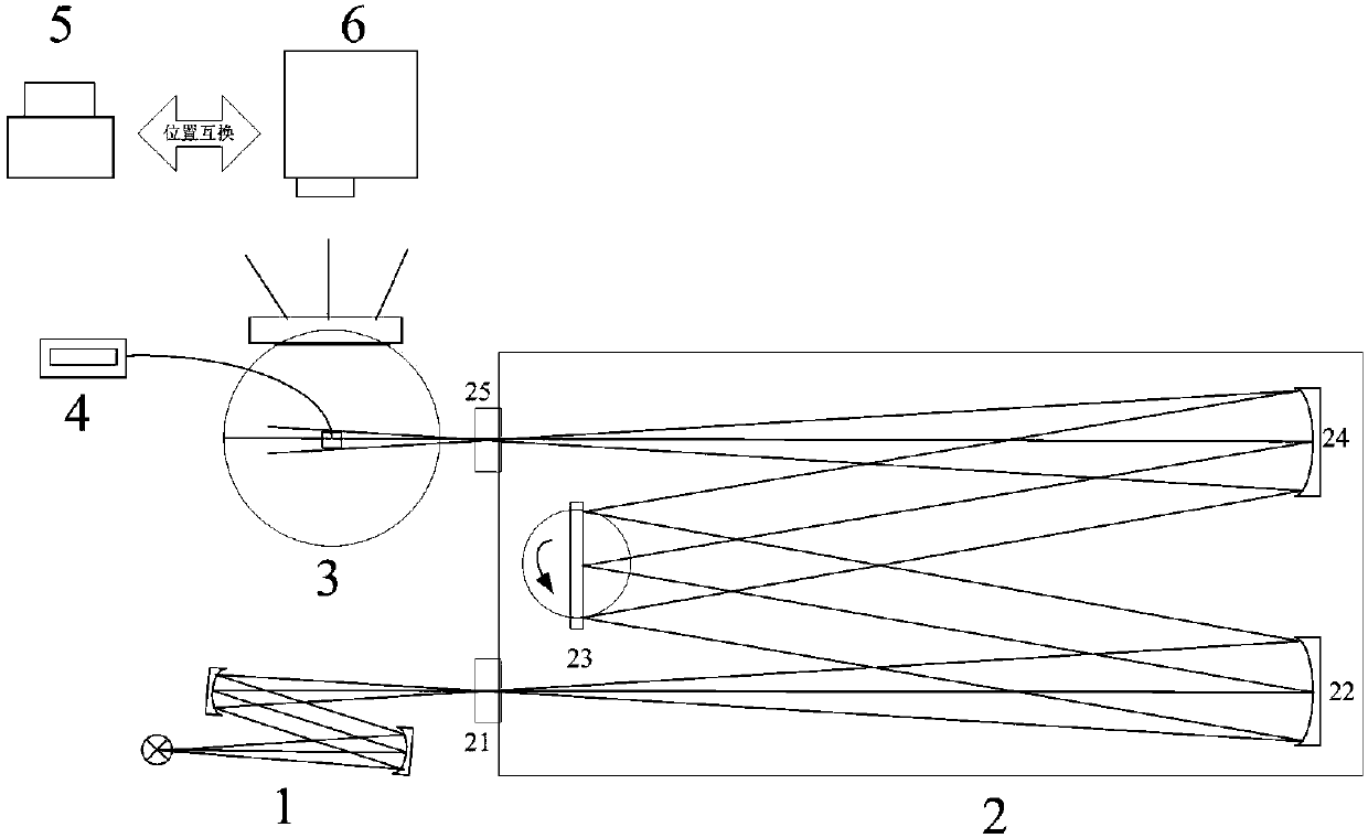
[0038] An imaging spectrometer spectral stray light correction algorithm of the known target relative spectral distribution of the present invention is realized by the imaging spectrometer spectral stray light measurement system. Such as figure 1 As shown, said imaging spectrometer spectral stray light measurement system is mainly composed of high stability and high brightness light source system 1, high precision monochromator 2, integrating sphere system 3, spectral radiance adjustment and monitoring system 4, absolute radiometer 5 and an imaging spectrometer 6 to be tested. The imaging spectrometer spectral stray light measurement system uses a high-stable and high-brightness light source system 1 to send out high-intensity continuous spectral signals, and outputs high-purity monochromatic light (the stray light coefficient is less than 10 -5 ), the high...


PUM


Abstract

The invention discloses an imaging spectrometer spectral stray light correction algorithm of known target relative spectral distribution, and belongs to the field of imaging spectrometer detection, aiming at removing the influence on the result from measuring imaging spectrometer by stray light. According to the invention, the algorithm includes the following steps: based on the influence on a to-be-detected imaging spectrometer by spectral stray light, using a monochromator to output a series of uniform lights which successfully enter and fills the field of view of the to-be-detected imagingspectrometer, using an absolute radiometer to record the energy of a series of monochromatic light spectrums, performing calculation to obtain a regression spectral response function of respective pixel of the to-be-detected imaging spectrometer; then calculating the ratio between effective spectral signals and total signals in respective pixel response signal in combination with the target relative spectral distribution, and eventually multiplying the real-measured signal with the proportion of the effective spectral signals so as to obtain an effective spectral signal, thus completing the spectral stray light correction on the to-be-detected imaging spectrometer. According to the invention, the algorithm has the characteristics of high measurement precision, simple computation, easy programming and easy real-time computing.

Description

technical field [0001] The invention belongs to the technical field of imaging spectrometer detection, and in particular relates to an imaging spectrometer spectral stray light correction algorithm with known target relative spectral distribution. Background technique [0002] Since it can detect the spatial information and spectral information of the observation target at the same time, the imaging spectrometer has been widely used in various fields such as atmospheric remote sensing, ground object spectral distribution and identification, and biomedicine in recent years, and the level of stray light is one of the imaging spectrometers. Important indicators, especially in quantitative research, stray light has become one of the key factors that limit the detection accuracy of imaging spectrometers. Stray light in the general sense includes spatial stray light and spectral stray light. For imaging spectrometers, spectral stray light is mainly considered in the design and pro...

Claims


Application Information

Patent Timeline
IPC IPC(8): G01J3/44
Inventor 李占峰王淑荣黄煜薛庆生
Owner CHANGCHUN INST OF OPTICS FINE MECHANICS & PHYSICS CHINESE ACAD OF SCI
Learn More