Solid-liquid separating device and solid-liquid separating process with filtering and air separating machine

A filtration device and solid-liquid separation technology, applied in the direction of filtration separation, separation method, filtration circuit, etc., can solve problems such as difficult tailings treatment, achieve thorough and clean dehydration, reduce hazards, and improve the quality of solid-liquid separation Effect

Inactive Publication Date: 2009-09-30
LUOYANG HUAYE GENERAL MACHINERY COMPLETE MFG
View PDF0 Cites 19 Cited by
  • Summary
  • Abstract
  • Description
  • Claims
  • Application Information

AI Technical Summary

Problems solved by technology

[0004] In order to solve the above-mentioned difficult problem of tailings treatment, the present invention provides a filtration and gas separator solid-liquid separation device and process, which can effectively filter tailings and water and perform air separation

Method used


Image

  • Solid-liquid separating device and solid-liquid separating process with filtering and air separating machine
  • Solid-liquid separating device and solid-liquid separating process with filtering and air separating machine

Examples


Embodiment 1

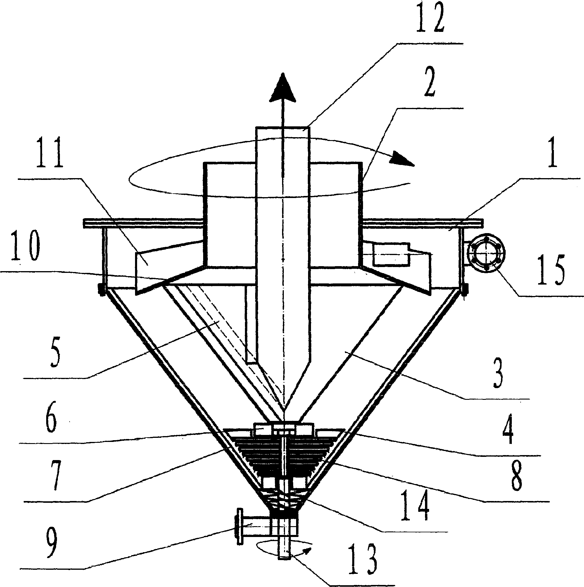
[0016] The sedimentation tank 1 is a cylindrical cone, the cylindrical part of the cylindrical cone is provided with a hollow shaft 2, the lower part of the hollow shaft 2 is provided with a diversion centrifugal device 11, and a limit cone bottom plate 10 is set below the flow diversion centrifugal device 11, and the limit cone bottom plate A filter device 3 is arranged below the filter device 3, a self-cleaning device 5 is arranged on the inner side of the cone surface of the filter device 3, a stop plate 6 is arranged under the filter device 3, and a nut is arranged under the stop plate 6; The device 7 and the inner side of the oblique cone surface of the cylindrical cone form a spiral shape; a gas separation device 8 is arranged under the swirl pressing plate 4, a hollow shaft 13 is arranged in the middle hole of the gas separation device 8, and a spiral extrusion device 14 is arranged under the gas separation device 8 A slag outlet 9 is provided at the bottom of the cylind...

Embodiment 2

[0018] As shown in Figure (1), the filter gas and separator are composed of a cylindrical conical sedimentation tank 1 and a centrifugal power vacuum shaft 2 on the upper cover, a vacuum device 12, a slag outlet in the middle of the lower part of the cone and a screw extrusion device 14 brackets. The upper rotation center hollow shaft 2 support plate of the sedimentation tank 1 is connected with a diversion centrifugal device 11 plate that can rotate around the axis and a filter device 3 mesh core connected to the bottom plate 10 of the limiting cone; the tailings entering the sedimentation tank 1 The sludge flows through the diversion centrifugal device 11, driven by the high-speed rotation of the diversion centrifugal device 11, and enters the centrifugal state, and the particles are centrifuged to the cone wall of the sedimentation tank 1; multiple slag guide devices are installed on the cone wall of the sedimentation tank 1 7 spiral guide plate, make the tailings settle qui...

Embodiment 3

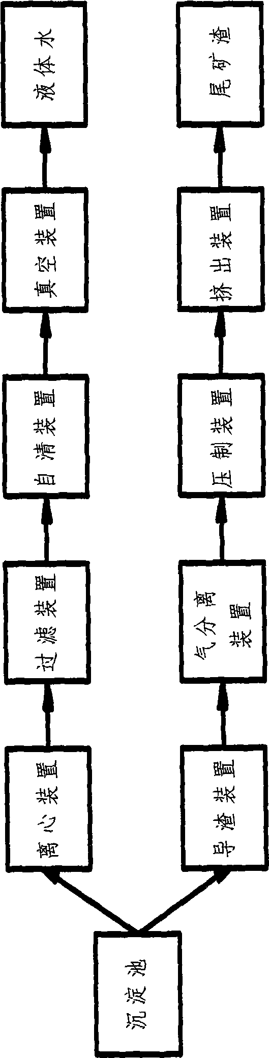
[0024] As shown in Figure (2), the process steps of solid-liquid separation using filtration and gas separator are as follows: the tailings muddy water enters the sedimentation tank 1 through the tailings inlet 15, generates centrifugal force through the diversion centrifugal device 11, and settles along the cone into the sedimentation tank 1. inside the cone. The separated water rotates to the filter element of the filter device 3, enters it after being filtered, is sucked away by the vacuum tube 12, and is discharged from the upper water outlet through power compression for recycling. The fine matter adhering to the space of the filter element of the filter device 3 is brushed off under the barrier of the plate of the self-cleaning device 5 .

[0025] The centrifuged tailings sludge quickly settles along the multiple rotating plates 7 of the cone into the chamber of the gas separation device 8, and the high-pressure gas squeezes out the water in the sediment, and the gas rep...


PUM


Abstract

The invention relates to a solid-liquid separating device and a solid-liquid separating process with a filtering and air separating machine. The solid-liquid separating device consists of a sedimentation tank 1, a central hollow shaft 2, a filtering device 3, a swirl flow pressboard 4, a self-cleaning device 5, a stop plate 6, a slag guide device 7, an air separating device 8, a slag outlet 9, a limiting flat cone plate 10, a flow guide centrifugal device 11, a vacuum tube 12, a hollow shaft 13, a helical extrusion device 14 and a tailing inlet 15. The solid-liquid separating process with a filtering and air separating machine can greatly improve solid-liquid separation quality, discharge water molecules under the action of a high-pressure air flow, allow ultrafine particles to enter space between large particles, achieve close combined by extrusion, make the dewatering more complete and more cleanly, and greatly reduce the infection density of a tailing dam and project invention.

Description

technical field [0001] The invention relates to a separation device and process, in particular to a filter and gas separator solid-liquid separation device and process. Background technique [0002] At present, the existing tailings treatment is: spend 20%-60% of the total investment in mining resources to build a tailings dam for accumulation and sedimentation, and then pump out the water that emerges from the upper surface after sedimentation for reuse, which is a huge investment. Moreover, the mixture of tailings and water in the tailings dam is extremely fluid, and once the dam breaks, it will cause a vicious accident on earth. Tailings mudslides have occurred frequently in various countries in the world, destroying many houses and buildings, killing many innocent lives, and submerging a lot of fertile land. [0003] Some domestic enterprises use large-scale concentration pools, high-power vacuum filters and other large-scale equipment to carry out solid-liquid separati...

Claims


Application Information

Patent Timeline
Patent Type & Authority Applications(China)
IPC IPC(8): B01D36/04
Inventor 郭亚非
Owner LUOYANG HUAYE GENERAL MACHINERY COMPLETE MFG
Why Eureka
Try Eureka