Micro-vibration auxiliary cutting device and method for brittle material

A technology of brittle materials and cutting methods, applied in the direction of stone processing tools, stone processing equipment, manufacturing tools, etc., can solve the problems of poor fracture, inability to cut, insufficient depth, etc., and achieve the effect of low cost and simple structure

Inactive Publication Date: 2009-09-30
CONTREL TECH CO LTD
View PDF0 Cites 13 Cited by
  • Summary
  • Abstract
  • Description
  • Claims
  • Application Information

AI Technical Summary

Problems solved by technology

However, with the hardness of a single light-transmitting substrate, the cutting depth of tungsten carbide or diamond cutter wheel is also different, especially for objects with higher hardness or thicker, sometimes the cutting depth will be in

Method used


Image

  • Micro-vibration auxiliary cutting device and method for brittle material
  • Micro-vibration auxiliary cutting device and method for brittle material
  • Micro-vibration auxiliary cutting device and method for brittle material

Examples


no. 1 example

[0060] refer to Figure 15 , about a micro-vibration-assisted cutting method for brittle materials of the present invention, its first embodiment includes the following steps:

[0061] 1. Preparation Step 41: If Figure 5 As shown, a workpiece fixing part 10, an initial cutting part 20 and a vibration cutting generating part 30 are prepared; wherein, the workpiece fixing part 10 is used to fix a workpiece 80 to be cut and belonging to a brittle material, and the workpiece 80 has a Working plane 81 and a predetermined workpiece thickness T1; the vibration cutting generating part 30 has a vibration generating part 31 and a vibration contact part 32; the vibration generating part 31 is used to generate a micro vibration of predetermined frequency, and the reciprocating The direction of vibration is substantially perpendicular to the working plane 81 (see Figure 11 ); There is a separation distance S between the vibration cutting generating part 30 and the initial cutting part ...


PUM


Abstract

The invention relates to a micro-vibration auxiliary cutting device and a method for a brittle material. The method partially comprises the following steps: 1, a preparation step; 2, an initial cutting step; 3, a slot-following vibration step; and 4, a completion step. Therefore, an initial kurf with a first depth on a workpiece on a workpiece fixing part is obtained through the cutting of an initial cutting part; and a vibration contact part moves along the initial kurf and simultaneously produces a slight amount of vibration which is perpendicular to the initial kurf and has a preset frequency, so that the first depth of the initial kurf is deepened to a second depth and the workpiece is further ruptured. Therefore, the cutting device simultaneously has the advantages of being applicable to harder and thicker workpieces to be cut, adopting a minor tungsten carbide or diamond knife flywheel, having a simple structure and low cost, and the like.

Description

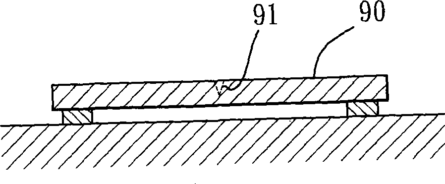
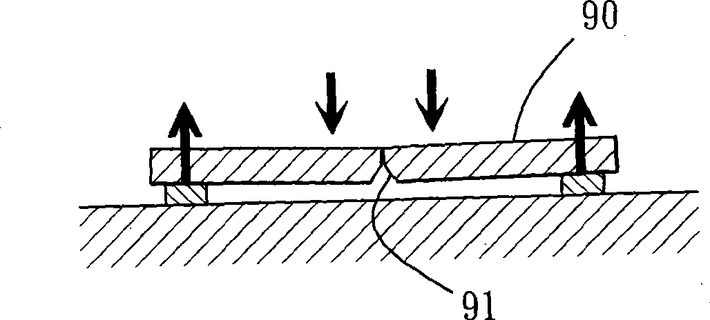
technical field [0001] The invention relates to a micro-vibration assisted cutting device and method for brittle materials. Background technique [0002] refer to figure 1 , regarding the cutting operation of traditional brittle materials, taking a single light-transmitting substrate 90 (especially a liquid crystal display panel) as an example, a tungsten carbide or diamond cutter wheel (not shown) is used to cut a cutting line on its upper surface 91. Then, turn over 180 degrees so that the cutting line 91 is located at the lower surface (as figure 2 shown). Next, apply a predetermined pressure or moment (such as image 3 arrow pointing down), that is, an action similar to pulling apart, the single transparent substrate 90 can be separated along the cutting line 91 to complete the cutting operation. [0003] Another traditional cutting method is to use the principle of the average force of air pressure, such as Figure 4 As shown, there is an upper light-transmitting...

Claims


Application Information

Patent Timeline
IPC IPC(8): B28D1/22
Inventor 郭佳笼陈彦桦
Owner CONTREL TECH CO LTD
Why Eureka
Try Eureka