Transmission box with gear clutch

A clutch and transmission box technology, applied in the transmission box field, can solve the problems of increasing the volume of the gearbox, failing to achieve the clutch effect, and unusable pulley clutches, etc., to achieve reduced impact, good running stability, and favorable power distribution. Effect

Active Publication Date: 2009-09-30
JIANGSU YUNMA AGRI MACHINERY
View PDF0 Cites 3 Cited by
  • Summary
  • Abstract
  • Description
  • Claims
  • Application Information

AI Technical Summary

Problems solved by technology

For example: Avoid oil, water, and dust in dry clutches. Once soaked in oil and water, the clutch will slip, and if it is polluted by dust, the clutch will be stuck and cannot work normally, and the pulley transmission mechanism is open or half-open. It is inevitable to be polluted by dust in the process of agricultural machinery operation, and the pulley clutch cannot be used for paddy field operations; wet clutches can be used for clutches in paddy field operations, but they have higher requirements on the oil condition in the clutch and are indispensable. Oil, otherwise

Method used


Image

  • Transmission box with gear clutch
  • Transmission box with gear clutch
  • Transmission box with gear clutch

Examples


Embodiment 1

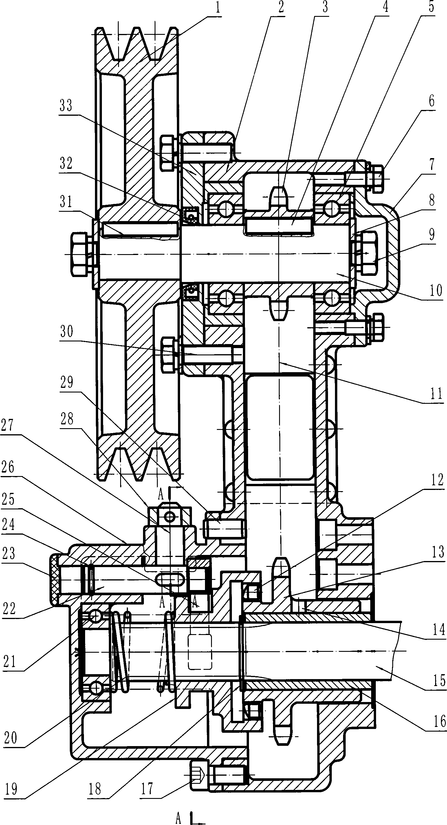
[0018] A chain transmission box with a toothed clutch, which includes a box body 2, the input shaft 10 is erected on the left and right side walls of the box body 2 through a set of bearings 5, and the driving sprocket 3 is arranged on the input side of the box body 2. On the shaft 10, the driving sprocket 3 is radially fixed to the input shaft 10 through the key 4. A shaft end cover 7 and a shaft cover 33 are respectively arranged on the outside of a set of bearings 5, the shaft end cover 7 is fixed on the box body 2 by a number of screws 6, the shaft cover 33 is fixed on the box body 2 by a number of screws 30, the shaft cover 33 is provided with a rotating lip seal ring 32 outside the shaft hole. The part of the input shaft 10 protruding from the casing 2 is provided with a driven pulley 1, and the driven pulley 1 is radially fixed to the input shaft 10 through a key 31. Both ends of the input shaft 10 are respectively fixed with retaining rings 8 by screws 9 .

[0019] O...

Embodiment 2

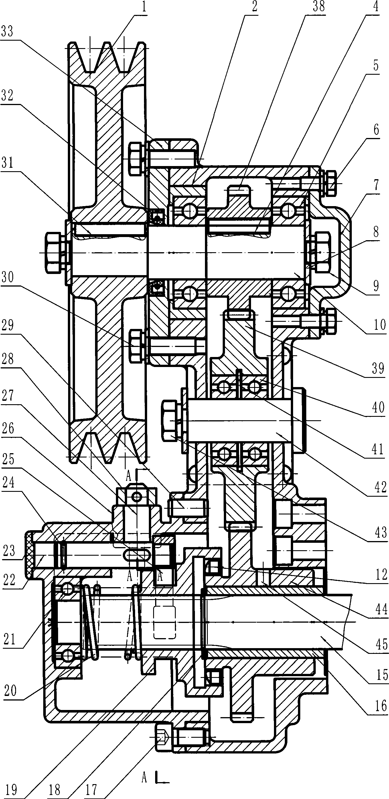
[0023] A gear transmission box with a toothed clutch, which includes a box body 2, the input shaft 10 is erected on the left and right side walls of the box body 2 through a set of bearings 5, and the driving gear 38 is arranged on the input shaft in the box body 2 10, the driving gear 38 is radially fixed with the input shaft 10 through the key 4. A shaft end cover 7 and a shaft cover 33 are respectively arranged on the outside of a set of bearings 5, the shaft end cover 7 is fixed on the box body 2 by a number of screws 6, the shaft cover 33 is fixed on the box body 2 by a number of screws 30, the shaft cover 33 is provided with a rotating lip seal ring 32 outside the shaft hole. The part of the input shaft 10 protruding from the casing 2 is provided with a driven pulley 1, and the driven pulley 1 is radially fixed to the input shaft 10 through a key 31. Both ends of the input shaft 10 are respectively fixed with retaining rings 8 by screws 9 .

[0024] One end of the outp...


PUM


Abstract

The invention provides a transmission box with a gear clutch, particularly a transmission box for transferring power to a hitching gearbox of an agricultural implement, belonging to the components of agricultural machinery. The transmission box comprises a box body, an input shaft, an output shaft, a driving wheel and a driven wheel, wherein the input shaft and the output shaft are mounted on the box body, the driving wheel is arranged on the input shaft and the driven wheel is arranged on the output shaft. The transmission box is characterized in that a gear clutch is arranged on the output shaft and near to one end outside the transmission box. The transmission box is beneficial to the power distribution of the hitching gearbox of the agricultural implement, can be used in paddy field and upland field, is free from clamp, slide and component damage, runs stably and is less impacted when being meshed.

Description

technical field [0001] The invention relates to a component of an agricultural machine, in particular to a transmission box for transmitting power to an agricultural machine coupled with a gear box. Background technique [0002] In the transmission mechanism of the existing tractor, it is usually a belt pulley that transmits power to the gearbox connected to the agricultural implement, and the clutch of the transmission mechanism usually adopts two kinds of ten-type clutch or wet clutch. If a dry clutch is used, it is usually installed on the pulley and combined into a pulley clutch; if a wet clutch is used, it is usually installed on the transmission shaft of the gearbox. In the actual production and use process, we found that they all have certain defects. For example: Avoid oil, water, and dust in dry clutches. Once soaked in oil and water, the clutch will slip, and if it is polluted by dust, the clutch will be stuck and cannot work normally, and the pulley transmission ...

Claims


Application Information

Patent Timeline
IPC IPC(8): F16H57/02F16H7/06F16H1/20F16H37/00F16D23/12F16D11/16F16H57/023
Inventor 季顺中吴耀东季自海杨根林李群
Owner JIANGSU YUNMA AGRI MACHINERY
Why Eureka
Try Eureka