Projection map display device

A technology of image display and components, applied in the field of projection image display devices, which can solve problems such as difficulty in dust, generation of bright spots and color spots, and reduction of brightness of projected images

Inactive Publication Date: 2009-09-30
HITACHI LTD +1
View PDF2 Cites 4 Cited by
  • Summary
  • Abstract
  • Description
  • Claims
  • Application Information

AI Technical Summary

Problems solved by technology

In the air blower equipped with this electrostatic dust collection mechanism, the dust ionized by one electrode is attracted and adsorbed by Coulomb force on the grid-shaped other electrode, but in order to improve the capture rate, the distance between the electrodes, Appropriate parameter settings for shape and applied voltage, however, it is extremely difficult to capture 100% of dust with different sizes and compositions
[0008] It can be clearly seen from the experimental results that the dust that invades the interior of the device through the air supply device equipped with an electric dust collection mechanism is ionized by the action of the above electric dust collection mechanism. State snapping can lead to serious performance issues such as reduced brightness, bright spots, and color mottling of projected images

Method used


Image

  • Projection map display device
  • Projection map display device
  • Projection map display device

Examples


Embodiment Construction

[0021] Hereinafter, the best mode for carrying out the present invention will be described with reference to the drawings. In addition, in each figure, elements having common functions are denoted by the same reference numerals, and descriptions of parts already explained are omitted.

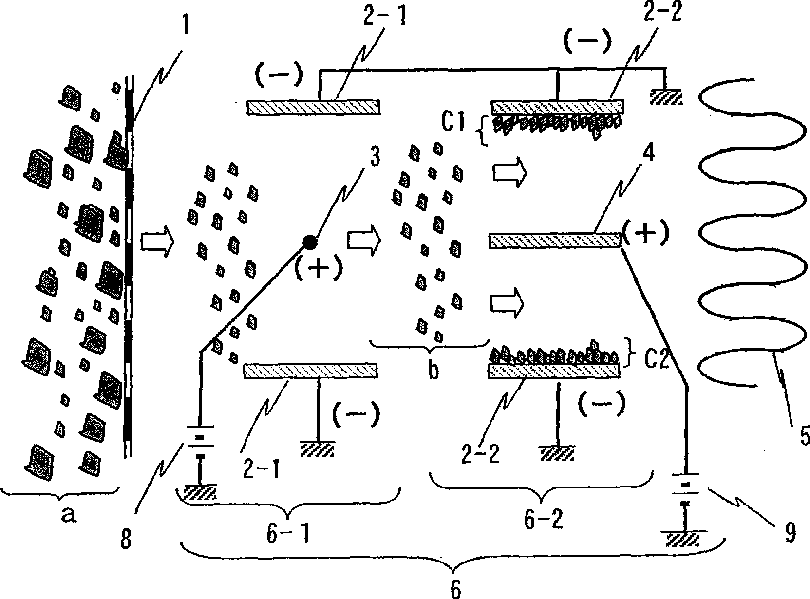
[0022] figure 1 It is a schematic diagram for explaining the principle of this embodiment easily. The mechanical dust removal filter 1 (coarse filter) provided on the main body of the device blocks relatively large (for example, 500 μm or more) dust among the dust a floating in the air. Next, a corona discharge is generated between the positive (high voltage) side electrode 3 of the high voltage power supply 8 provided on the charge unit 6-1 and the negative (ground) side electrode 2-1 thereof, so that the dust b is positively charged, and the dust b is positively charged in the current collection. The positive electrode (high voltage) side electrode 4 of the high voltage power supply 9 and t...


PUM


Abstract

A projection map display device is composed of rough filters configured in sequence at air feed direction for shading large-granule dust, a dust charge section composed of a discharge electrode and a relative electrode, a dust collection section composed of a high-voltage electrode collecting charged dust for the dust collection section and the dust collection electrode, a main filter mechanically sucking dust form air of the collection section and a fan blowing fed air, the fan is used for cooling a part of the illumination optical system members and a map display element. Further, conductive treatment is applied to the map display element and a part of the surface of the optical members to move the charge without conglutination even in condition that duct ionized and activated by the electric dust collection device passes through the main filter and contacts with the illumination optical system members composed of the map display element and optical members, thereby carrying out electric grounding treatment with the an electronic circuit.

Description

technical field [0001] The present invention relates to a projection-type image display device, which has an image display element and an illumination optical system. The light beam obtained by the illumination optical system is modulated by the image display element, and the image is projected on the screen, such as a liquid crystal projection device and a reflector type image display projection device, especially if an electric dust collection device and a mechanical dust removal filter or a mechanical dust removal filter and an electrostatic dust removal filter are installed at the air inlet for cooling the illumination optical system and the image display element Projection type image display device. Background technique [0002] The projection type image display device has the following structure, that is, the light beam emitted from the light source is modulated by the image display element, that is, the liquid crystal panel or the reflection type liquid crystal panel,...

Claims


Application Information

Patent Timeline
Patent Type & Authority Applications(China)
IPC IPC(8): G03B21/00H04N5/74H04N9/31
Inventor 平田浩二乾真朗真木教雄今中光三津森友则
Owner HITACHI LTD
Why Eureka
Try Eureka