Device for monitoring working state of fuse

A technology of working status and monitoring devices, which is applied in the direction of measuring devices, emergency protection devices for automatic disconnection, circuit devices, etc., can solve problems such as the adverse effects of restoring normal power supply, potential safety hazards of power supply lines, and damage to electrical facilities, etc. The inspection and elimination process is convenient, the safety protection factor is improved, and the effect of protecting electrical equipment

Inactive Publication Date: 2009-09-30
浙江三慧能源科技有限公司
View PDF0 Cites 18 Cited by
  • Summary
  • Abstract
  • Description
  • Claims
  • Application Information

AI Technical Summary

Problems solved by technology

However, there is generally no monitoring device, and the following disadvantages exist in actual use:
[0003] 1. When an overload current occurs in the transmission line and the fuse plays a role in safe fusing, since each transmission line is connected to multiple power consumption units or output terminals, the staff often need to check and eliminate the accident point and cause of the accident one by one , Time-consuming and labor-intensive is not conducive to the rapid recovery of line power supply status, and has a certain impact on normal power supply;
[0004] 2. When one of the three-phase power supplies of the transmission line is missing, the other two often cannot be fused or broken in time because the power supply current is not overloaded and continue to work. There will be safety problems in power transmission, and it will also cause damage to power facilities. damage;
[0005] 3. In the operating environment where the circuit breaker is in a heated state for a long time, there will be aging of the fuse parts or mechanical contact points. If the daily inspection is not in place or replaced in time, there will be safety hazards in the circuit due to failure
[0006] Due to the above defects, the power supply line has certain potential safety hazards, and when a fault occurs, it is not conducive to inspection and quick elimination, which will adversely affect the restoration of normal power supply as soon as possible.

Method used


Image

  • Device for monitoring working state of fuse
  • Device for monitoring working state of fuse

Examples


Embodiment Construction

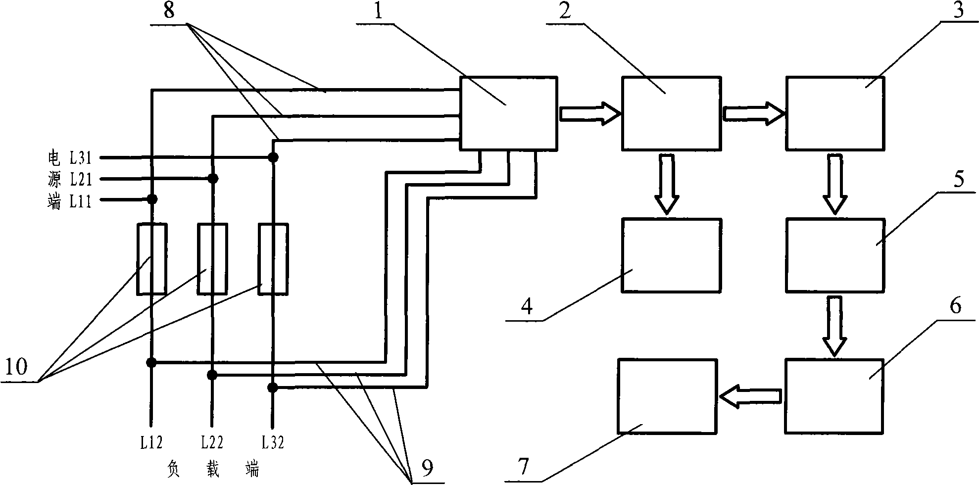
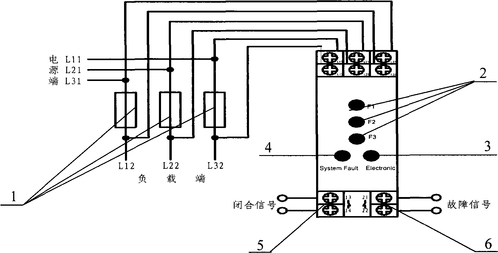
[0016] The fuse monitoring module of the present invention, according to the above design ideas, in terms of specific implementation, the monitoring signal of the three-phase fuse can be connected to the monitoring device of the fuse through the connecting plug-in, and the voltage signal at both ends of the fuse is passed through the resistor After the current is limited, it is connected to both ends of the light-emitting diode to indicate the working state of the fuse. The working voltage of the circuit board is taken from the fuse receiving end of the fuse monitoring signal, and is used as whether the three-phase power supply is missing and whether the fuse is blown. The signal of the three-phase AC power is sent to the voltage stabilizing circuit unit composed of resistors, Zener diodes and capacitors through diode rectification and capacitor filtering, and the output stabilized DC power supply is supplied to each functional unit. At the same time, the power indicator light-...


PUM


Abstract

The invention discloses a device for monitoring working or fusing state of a fuse, and relates to field of power transmission and distribution of power systems. The device for monitoring the working state of the fuse is connected in parallel near the fuse on a power transmission line. One end of the monitoring device is connected with a line load end, and the other end of the monitoring device is connected with a line power end. When the monitoring device monitors the information that the fuse in a three-phase power supply fuses and ages to be broken (no contact) or breaks down, comparison is carried out with the voltage in a monitoring module and after making judgment, the monitoring device sends a fault signal to give an alarm. At the same time, an indication output end sends the signal to electric equipment to cut off the power supply of the electric equipment so as to protect the electric equipment. The monitoring device improves the safety protection factor of a circuit and provides great convenience for the power transmission and distribution management of the power system.

Description

Technical field [0001] The invention relates to the field of power transmission and distribution of electric power systems, realizes the monitoring of the working or fusing state of fuses, can detect power line faults in time, realizes missing protection of power lines, and improves the safety and reliability of power distribution network operation. Background technique [0002] At present, in the power transmission and distribution safety protection system of the power system, a large number of fuses are used. In many cases, there are multiple sections of protection in one line, and each power facility and transmission terminal is protected by a fuse or a circuit breaker. And breaking, in order to prevent the impact of overload current on the line, transmission and distribution facilities and electrical equipment and cause damage, and prevent the occurrence of electrical safety accidents. However, there is generally no monitoring device, and the following disadvantages exis...

Claims


Application Information

Patent Timeline
Patent Type & Authority Applications(China)
IPC IPC(8): H02H3/253G01R31/07G01R31/74
Inventor 杨永明黄春芳程瑜
Owner 浙江三慧能源科技有限公司
Why Eureka
Try Eureka