Fluorescent lamp control circuit
A technology for controlling circuits and fluorescent lamps, applied to light sources, electric light sources, electrical components, etc., can solve the inconvenience of fluorescent lamps and achieve the effect of increasing luminous flux and increasing filament current
- Summary
- Abstract
- Description
- Claims
- Application Information
AI Technical Summary
Problems solved by technology
Method used
Image

Examples
Embodiment Construction
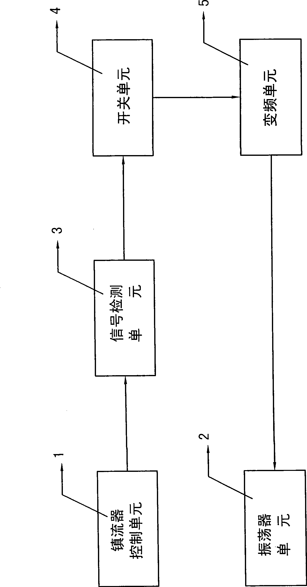
[0013] like figure 1 As shown, the fluorescent lamp control circuit of the present invention includes a ballast control unit 1, an oscillator unit 2, a signal detection unit 3, a switch unit 4 and a frequency conversion unit 5, and the signal detection unit 3 receives the ballast control unit 1 After turning on the signal, the signal is output to the switch unit 4, the switch unit 4 outputs the signal to the frequency conversion unit 5, and the frequency conversion unit 5 outputs the signal to the oscillator unit 2 to change the oscillation frequency.
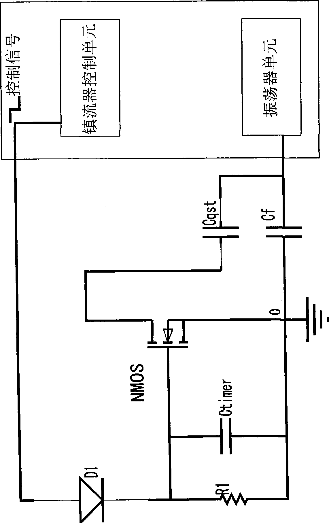
[0014] Preferably, as figure 2 As shown, the signal detection unit includes a diode D1, a resistor R1 and a capacitor Ctimer, the resistor R1 and the capacitor Ctimer are connected in parallel to the cathode of the diode D1, and the anode of the diode D1 is connected to the ballast control unit; The switch unit is an NMOS transistor, the gate of which is connected to the cathode of the diode D1, and the source is grounded; th...
PUM
 Abstract
Description
Claims
Application Information
 - R&D
- Intellectual Property
- Life Sciences
- Materials
- Tech Scout
- Unparalleled Data Quality
- Higher Quality Content
- 60% Fewer Hallucinations
Browse by: Latest US Patents, China's latest patents, Technical Efficacy Thesaurus, Application Domain, Technology Topic, Popular Technical Reports.
© 2025 PatSnap. All rights reserved.Legal|Privacy policy|Modern Slavery Act Transparency Statement|Sitemap|About US| Contact US: help@patsnap.com