Method and apparatus for biometric identification

A biological and biological imaging technology, applied in secure communication, electrical components, etc.

Inactive Publication Date: 2009-09-30
CERNI CONSULTING
View PDF7 Cites 13 Cited by
  • Summary
  • Abstract
  • Description
  • Claims
  • Application Information

AI Technical Summary

Problems solved by technology

[0014] The present invention achieves the first true non-contact manual measurement in which measurement errors caused by uncertainties in target range and horizontal registration are eliminated

Method used


Image

  • Method and apparatus for biometric identification
  • Method and apparatus for biometric identification
  • Method and apparatus for biometric identification

Examples


Embodiment Construction

[0028] 1. A preferred embodiment of palm vein pattern recognition

[0029] The detailed description of this preferred embodiment describes an electro-optical system and method for improving the performance of a subcutaneous vein pattern imager (preferably a hand vein imager, more preferably a palm vein imager) for biometrics . Those skilled in the art can easily modify the electro-optical device described in this section into a subcutaneous vein pattern imager designed to scan other parts of the human body. The hand vein imager includes an imager that images the veins of any part of the hand (including the palm, the back of the hand, or the front or back of any finger).

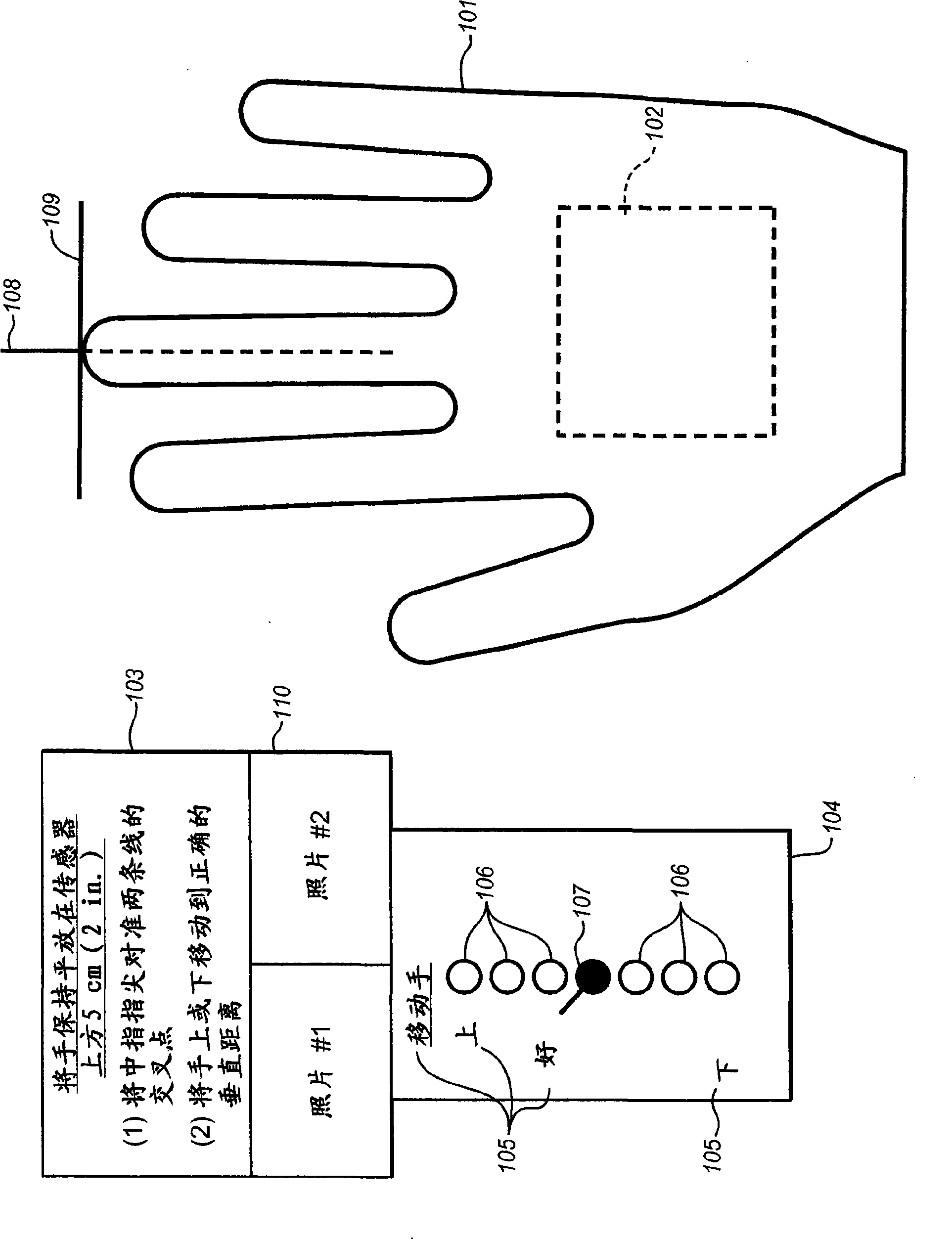
[0030] figure 1 It depicts how the biometric system is presented in front of the scanned individual; it shows a view looking down at the back of the right hand 101. The infrared imager module 102 is under the hand, so it is depicted with a dashed line. On the left side of the hand are the indicator block 103, t...


PUM


Abstract

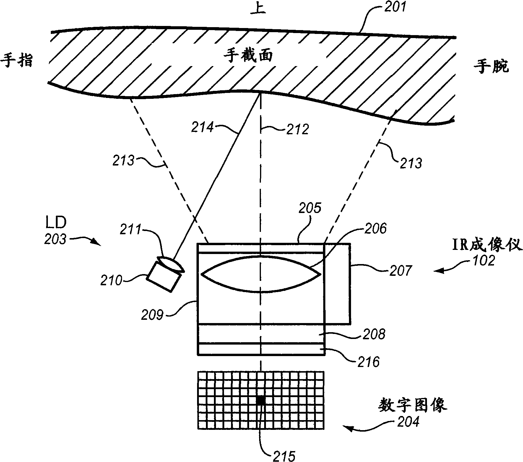
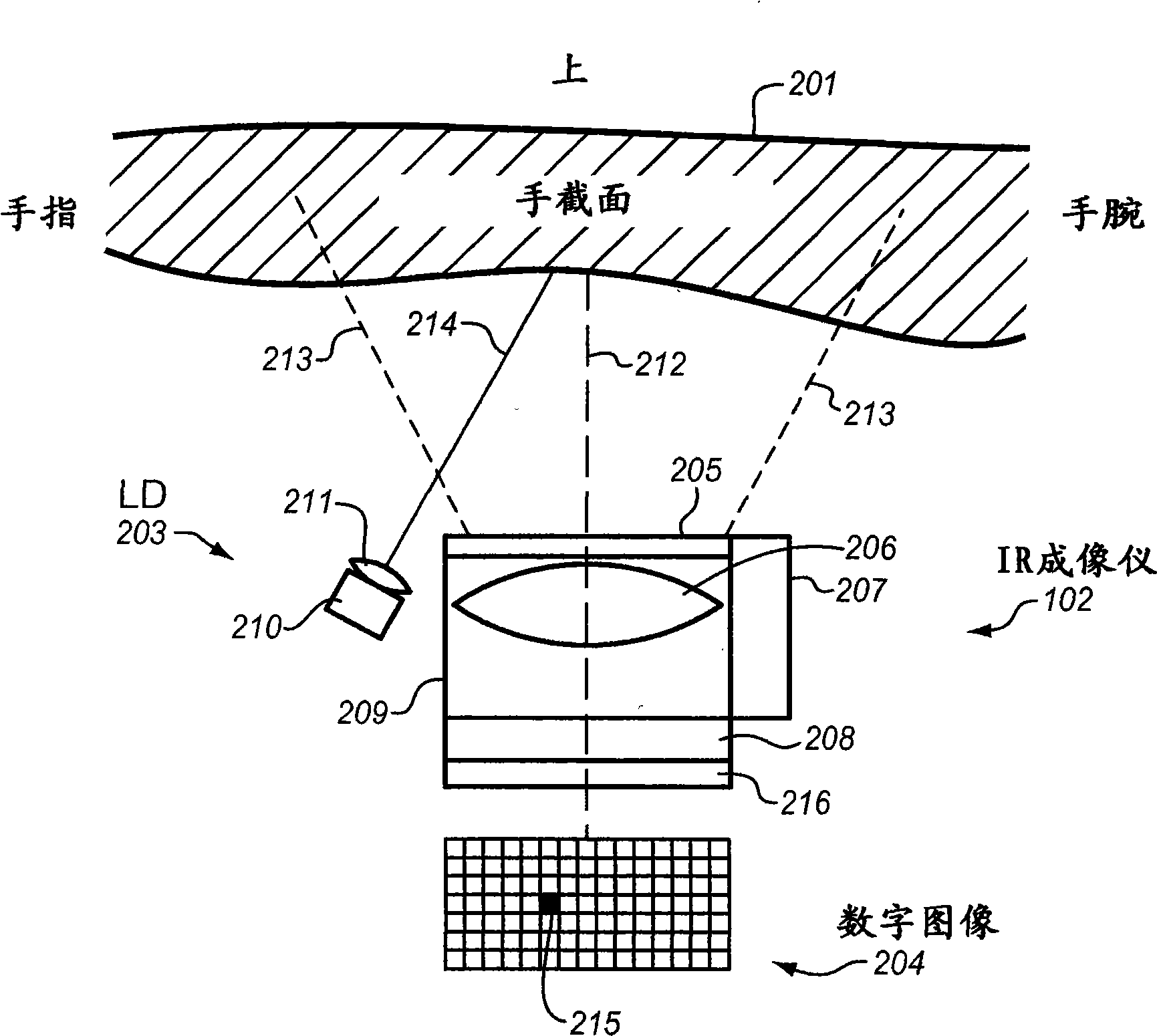
The invention describes the first practical, cost effective, truly non-contact implementation of a subcutaneous vein pattern biometric sensor. A laser diode (LD) illuminates the hand in such a way that the pattern of reflected radiation, when viewed by a conventional vein pattern infrared imager, provides a direct measure of target range. Said target range measurement is used to create a visual or audio signal that instructs the individual being scanned to place the hand at precisely the optimum range, such that the vein pattern is in focus. Furthermore, a system and apparatus are described to direct the individual being scanned to move the hand to an optimal horizontal registration or position with respect to the infrared imager.

Description

Technical field [0001] The present invention relates to individual biometric recognition using subcutaneous vein pattern recognition through infrared imaging of a part of the human body (most typically a part of the hand). Background technique [0002] Individual biometrics represent a small but rapidly growing commercial market. It is estimated that the market for biosensors and systems will reach US$4 billion by 2008. Motivations for increased use of biometrics include any anti-terrorism screening (for example, screening of air passengers and access control at government facilities and commercial facilities), plus protection against identity theft caused by theft of financial account numbers and passwords. Regarding the latter, some major banks have installed biometric identification systems at their ATMs. Each user records his or her biometrics on the data card, and must match the pattern in real time by scanning the individual's bio before allowing access to the bank account....

Claims


Application Information

Patent Timeline
IPC IPC(8): H04K1/00
Inventor 托德·A·切尔尼
Owner CERNI CONSULTING
Why Eureka
Try Eureka