
Large turning angle positioning vacuum chuck

A technology of vacuum suction cups and large rotation angles, which is applied to suction cups, suction cup devices with large rotation angles and high-precision positioning requirements, and the field of vacuum suction cups with large rotation angles, which can solve the problems of unusable positioning, large number of mold tires, and long preparation period, etc., to achieve The effects of ensuring positioning accuracy, expanding the scope of use, and improving production efficiency

Inactive Publication Date: 2009-10-07
SHENYANG AEROSPACE UNIVERSITY
View PDF0 Cites 10 Cited by
  • Summary
  • Abstract
  • Description
  • Claims
  • Application Information

AI Technical Summary

Problems solved by technology

The number of molds is large, the cost is high, and the preparation period is long. Therefore, the special design of fixtures according to a single variety can no longer meet the needs of production development. Therefore, the trend of tooling flexibility is imperative.
The use of suction cup flexible tooling is a better solution, in which the suction cup is a key component. The suction cup used in the flexible tooling should have dual functions of positioning and adsorption. In order to maintain the correct shape of the sheet metal parts, the suction cup is required to be able to rotate, and The corner is large, and the suction cups currently used are generally fixed suction cups, which can only play the role of adsorption and fixation, and cannot be used for positioning. When used, a special positioning structure is required to cooperate with it, resulting in increased costs and poor versatility.
At present, the structure of the suction cup used abroad is complex, and errors may occur in the case of small corners

Method used


Image

  • Large turning angle positioning vacuum chuck
  • Large turning angle positioning vacuum chuck

Examples


Embodiment Construction

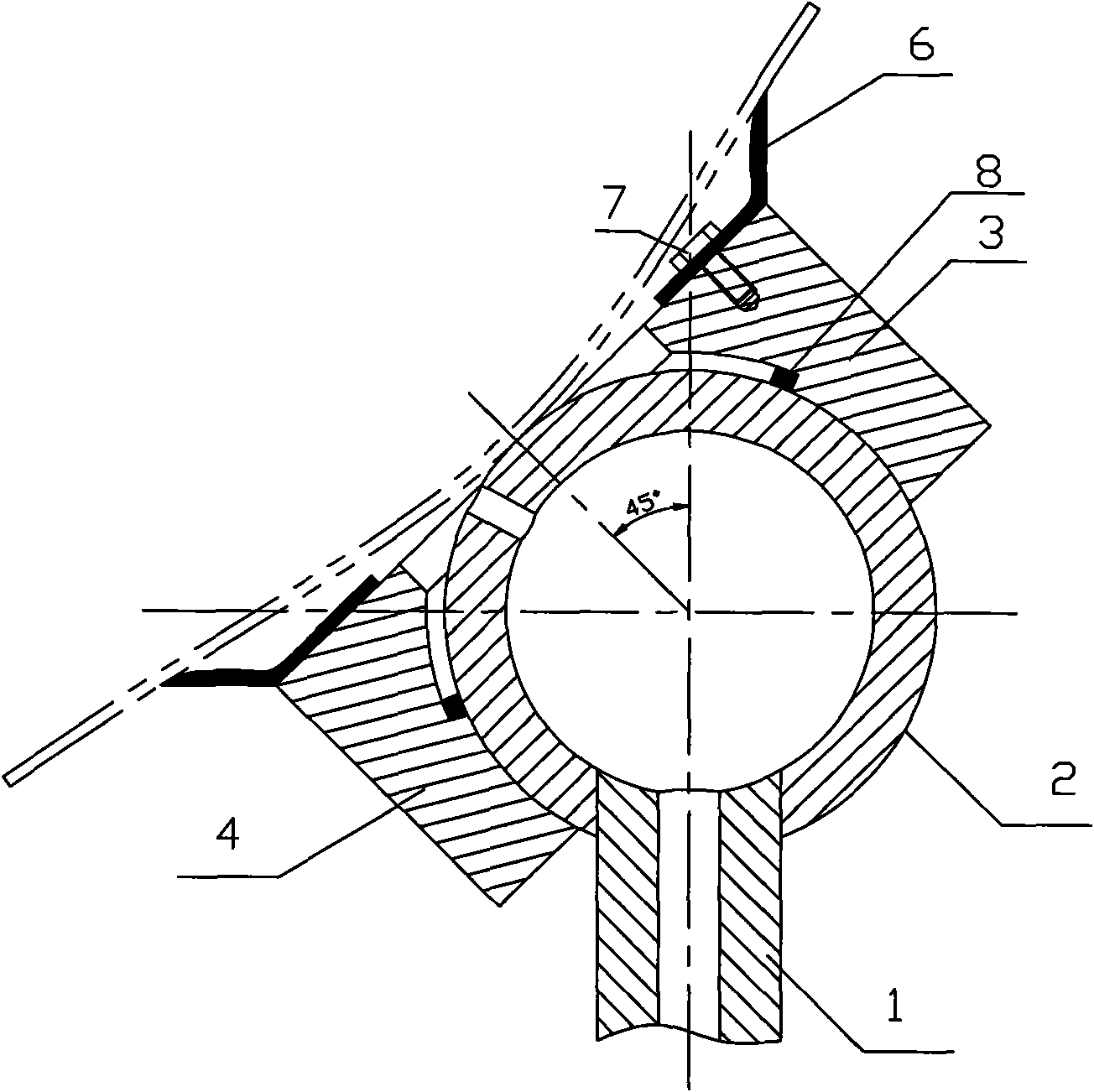
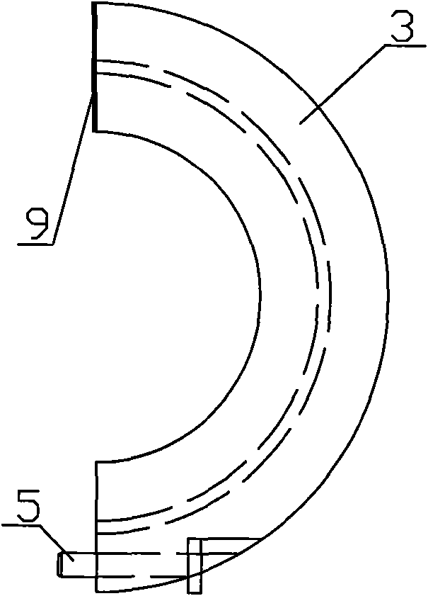
[0008] Such as Figure 1-Figure 2 As shown, the large rotation angle positioning vacuum suction cup includes a suction cup seat 1, a positioning ball 2, a rotating block A3, a rotating block B4, a bolt A5, a sealant bowl 6, a bolt B7, a sealing strip A8 and a sealing strip B9. The suction cup seat 1 is connected with the positioning ball 2, and the rotating block A3 and the rotating block B4 are connected together by the bolt A5, and the inner surface forms a spherical surface to cooperate with the positioning ball to slide. The seal between the rotating block A3 and the rotating block B4 is sealed by the sealing strip B9, and the spherical sealing is realized between the sealing strip A8 and the positioning ball 2 . The sealant bowl 6 is connected with the rotating block 3A and the rotating block B4 through the bolt B7.

[0009] Working principle: The positioning ball 2 can support and accurately locate the sheet metal parts, and the holes in it are used for vacuuming. The ...


PUM


Abstract

The invention discloses a large turning angle positioning vacuum chuck which comprises a chuck base, a positioning ball, a turning block A, a turning block B, a bolt A, a sealing rubber cup, a bolt B, a sealing strip A and a sealing strip B. The chuck base is connected with the positioning ball, the turning block A and the turning block B are connected together by the bolt A, the inner surfaces thereof form a spherical surface which slide coordinately with the positioning ball. The turning block A and the turning block B are sealed by the sealing strip B, the turning block A, the turning block B and the positioning ball are spherically sealed by the sealing strip A. The sealing rubber cup is connected with the turning block A and the turning block B by the bolt B. The chuck adopts the positioning ball to carry out point positioning so as to ensure positioning accuracy, thereby realizing large angle turning of the chuck, being suitable for the process of sheet metal parts with different curvatures, enlarging the serviceable range of machine tools, solving the problem of numerous tooling during process of edge trimming of the sheet metal parts and the like, increasing the flexibility of tooling, and improving the production efficiency.

Description

Technical field: [0001] The invention relates to a suction cup, in particular to a large-rotation-angle positioning vacuum suction cup, which belongs to the field of machining tools, in particular to a suction cup device used in the field of flexible support tooling with large-rotation angle and high-precision positioning requirements. Background technique: [0002] Ensuring the processing precision of thin-walled parts mainly depends on two factors, one is high-precision machine tools, such as CNC milling, laser cutting machines, etc.; the other is fixtures. Among them, high-precision trimming machine tools are already available, and the fixtures need to be designed and manufactured. Among them, suction cup flexible tooling is an optimized choice. There are many types of thin plate structures, and the traditional method is to use special mold tires for support and fixation. The number of molds is large, the cost is high, and the preparation period is long. Therefore, the ...

Claims


Application Information

Patent Timeline
IPC IPC(8): B25B11/00B23Q3/00
Inventor 韩志仁刘春
Owner SHENYANG AEROSPACE UNIVERSITY
Learn More