Special-purpose collecting component for cotton type siro spinning

A collector and siro spinning technology, applied in the field of collector components, can solve the problems of excessive hairiness, inability to apply siro spinning, weak strength, etc., to achieve easy end breakage, reduce siro spinning hairiness, and enhance strength. Effect

Inactive Publication Date: 2009-10-07
童云章
View PDF0 Cites 9 Cited by
  • Summary
  • Abstract
  • Description
  • Claims
  • Application Information

AI Technical Summary

Problems solved by technology

Due to the limitation of the structure, the existing concentrator cannot be applied to the siro-spun yarn, so the siro-spun yarn has many shortcomings such as hairiness and weak strength.

Method used


Image

  • Special-purpose collecting component for cotton type siro spinning
  • Special-purpose collecting component for cotton type siro spinning
  • Special-purpose collecting component for cotton type siro spinning

Examples


Embodiment 1

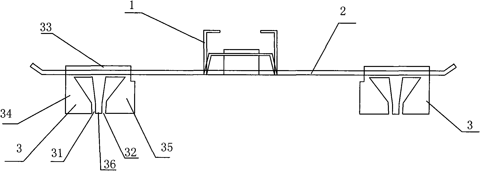
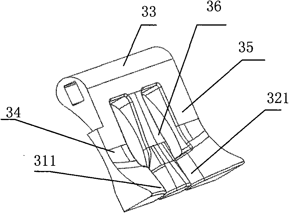
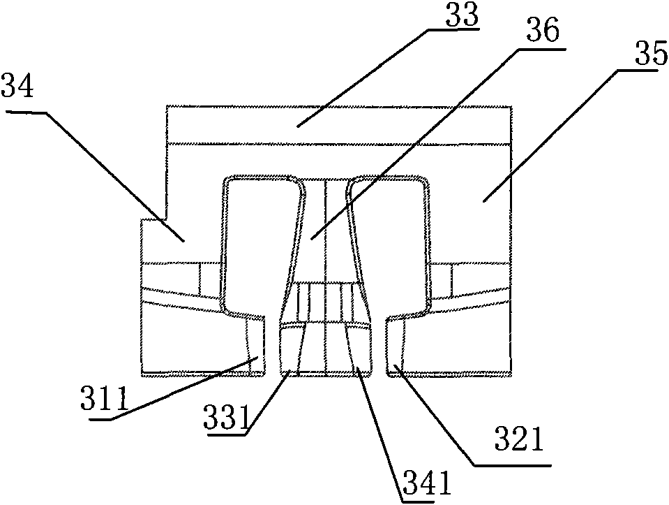
[0017] Embodiment 1: A collector assembly dedicated to cotton siro spinning, including a steel wire hook 1, a connecting shaft 2 and two collectors 3, the steel wire hook 1 is located in the middle of the connecting shaft 2, and the collectors 3 are respectively arranged on the connection On both sides of the shaft 2, the concentrator 3 is provided with A cluster port 31 and B cluster port 32 which are isolated from each other. The width of the A cluster port 31 or the B cluster port 32 is 1.5mm, and the center distance between the A cluster port 31 and the B cluster port 32 is 4mm. The width of the cluster port A is equal to that of the cluster port B. The concentrator includes a crosspiece 33, an A vertical piece 34, a B vertical piece 35, and an intermediate piece 36. The crosspiece 33 is passed on the connecting shaft 2, and the lower end of the A vertical piece 34 extends toward the middle direction and forms an A cluster opening 31 with the middle piece 36. The lower en...

Embodiment 2

[0020] Embodiment 2: A collector assembly dedicated to cotton siro spinning, including a steel wire hook 1, a connecting shaft 2 and two collectors 3, the steel wire hook 1 is located in the middle of the connecting shaft 2, and the collectors 3 are respectively arranged on the connection On both sides of the shaft 2, the concentrator 3 is provided with A cluster port 31 and B cluster port 32 which are isolated from each other. The width of the A cluster port 31 or the B cluster port 32 is 2 mm, and the center distance between the A cluster port 31 and the B cluster port 32 is 7mm. The width of the cluster port A is equal to that of the cluster port B. The concentrator includes a crosspiece 33, an A vertical piece 34, a B vertical piece 35, and an intermediate piece 36. The crosspiece 33 is passed on the connecting shaft 2, and the lower end of the A vertical piece 34 extends toward the middle direction and forms an A cluster opening 31 with the middle piece 36. The lower end...

Embodiment 3

[0021] Embodiment 3: A collector assembly dedicated to cotton siro spinning, including a steel wire hook 1, a connecting shaft 2 and two collectors 3, the steel wire hook 1 is located in the middle of the connecting shaft 2, and the collectors 3 are respectively arranged on the connection On both sides of the shaft 2, the concentrator 3 is provided with A cluster port 31 and B cluster port 32 which are isolated from each other. The width of the A cluster port 31 or the B cluster port 32 is 2.5mm, and the center distance between the A cluster port 31 and the B cluster port 32 is 11mm. The width of the cluster port A is equal to that of the cluster port B. The concentrator includes a crosspiece 33, an A vertical piece 34, a B vertical piece 35, and an intermediate piece 36. The crosspiece 33 is passed on the connecting shaft 2, and the lower end of the A vertical piece 34 extends toward the middle direction and forms an A cluster opening 31 with the middle piece 36. The lower e...


PUM

PropertyMeasurementUnit
Widthaaaaaaaaaa
Center distanceaaaaaaaaaa

Abstract

The invention discloses a special-purpose collecting component for cotton type siro spinning, which comprises a steel wire hook, a connecting shaft and two collecting devices; the steel wire hook is positioned on the middle of the connecting shaft; and the collecting devices are disposed respectively on two sides of the connecting shaft. The invention is characterized in that: the collecting device is disposed with an A clustering port and a B clustering port which are isolated from each other; the width of the A or B clustering port is 1mm-3mm; and the center distance of the A and B clustering port is 3mm-11.5mm. Advantages: by disposing two isolated clustering ports on the collecting device and designing the width of the A or B clustering port as 1mm-3mm, the invention can cluster fibers effectively and reduce the siro spinning hairiness; and the center distance of the A and B clustering port is 3mm-11.5mm, two yarns is drawn by the front leather roller, then is respectively passed the A clustering port and the B clustering port, and the two yarns from respectively from the A clustering port and the B clustering port with even stresses form a larger triangle area with the jointing point, thereby, the invention achieves better twisting effect, improves siro yarn strength, and further reduces the siro spinning hairiness.

Description

technical field [0001] The invention relates to a textile machinery accessory, in particular to a collector assembly used in cotton siro spinning. Background technique [0002] The spinning principle of cotton siro spinning is that two rovings are introduced into the drafting area of ​​the spinning frame through the double bell mouth, drawn in a parallel state, and form two fiber bundles at a certain distance after coming out of the front top roller clamping point. The strand fiber bundles are lightly twisted for the first time in the triangular area, and then merged at the joint point, then twisted again and taken up on the bobbin to become a twin-spun yarn. The concentrator used in the traditional spinning process plays a role in concentrating the fiber bundles, which can reduce yarn hairiness and enhance yarn strength. The existing concentrator cannot be applied to the siro-spun yarn due to the limitation of the structure, so the yarn formed by the siro-spun yarn has man...

Claims


Application Information

Patent Timeline
IPC IPC(8): D01H5/72
Inventor 童云章
Owner 童云章
Why Eureka
Try Eureka