

Light-emitting device and backlight device using the same and assembling method
A light-emitting device and a technology of a light-emitting unit, which are applied to components of lighting devices, optical elements for changing the spectral characteristics of emitted light, and damage prevention measures for lighting devices, and can solve problems such as difficult heat removal, low and high luminance, etc. question
- Summary
- Abstract
- Description
- Claims
- Application Information
AI Technical Summary
Problems solved by technology
Method used
Image

Examples
Embodiment 1
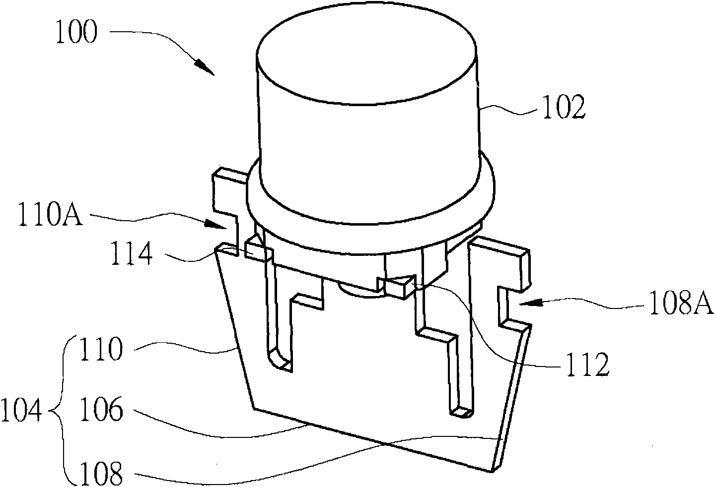
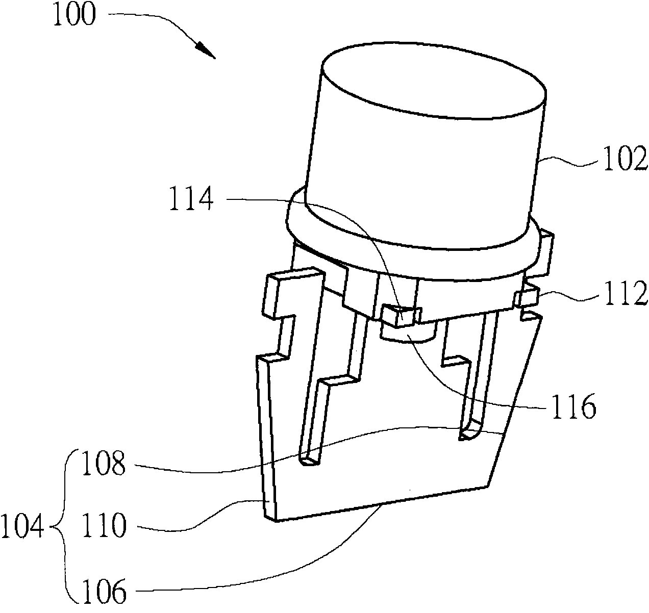
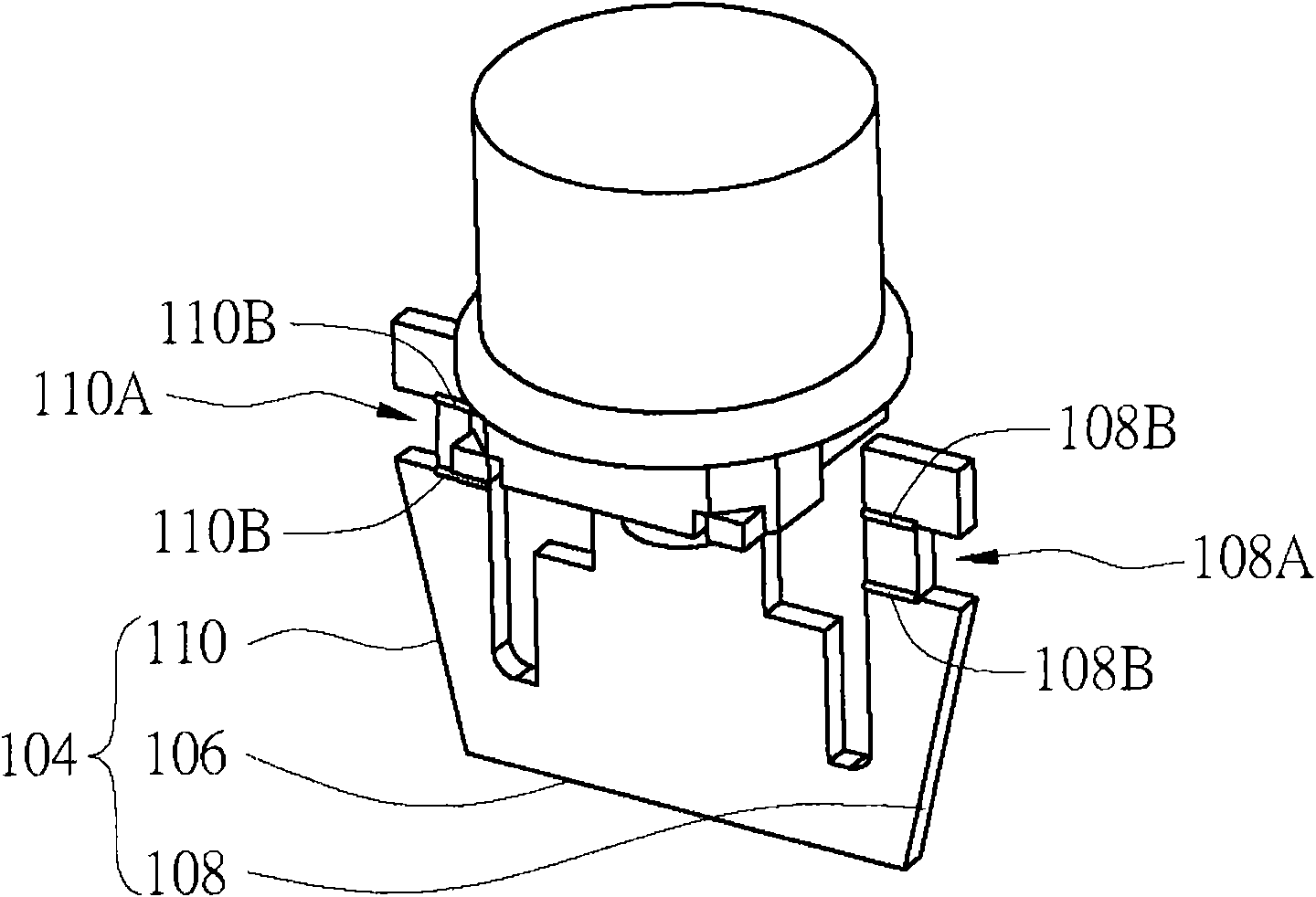
[0141] Please refer to Figure 1A , 1B , which respectively show the schematic diagrams of the light emitting device with assembly and positioning function according to Embodiment 1 of the present invention under different viewing angles. The light emitting device 100 includes a light emitting unit 102 and a supporting bracket 104 . The supporting bracket 104 includes a plate body 106 and at least one positioning arm. In this embodiment, the supporting bracket 104 has two positioning arms 108 and 110 as an example for illustration. One end of the board 106 is connected to the light emitting unit 102 , and two positioning arms 108 , 110 are connected to the other end of the board 106 , and the positioning arms 108 , 110 extend toward the light emitting unit 102 . Preferably, the two positioning arms 108 , 110 are disposed symmetrically to the board body 106 .
[0142] Since the positioning arms 108 , 110 extend upward from the bottom of the board 106 , the positioning arms 10...
Embodiment 2
[0164] Please refer to Figure 4A , which is a schematic diagram of a light-emitting device with uniform luminance according to Embodiment 2 of the present invention. The light emitting device 200 includes a light emitting unit 202 , a supporting bracket 204 , a transparent package 206 and a fluorescent colloid layer 208 . The light emitting unit 202 is disposed on the supporting frame 204 . The transparent encapsulation 206 covers the light emitting unit 202 , and the outer side of the transparent encapsulation 206 has a recess. The transparent encapsulation body 206 has at least one reflective surface 206A in its concave portion. The fluorescent colloid layer 208 is disposed outside the transparent package 206 , and the fluorescent colloid layer 208 and the concave portion of the transparent package 206 form an air chamber 210 . Wherein, the reflective surface 206A of the transparent package 206 is used to guide the light generated by the light emitting unit 202 to the si...
Embodiment 3
[0211] The stacked light emitting device of this embodiment includes a main body support, at least one heat dissipation support and at least one light emitting unit, wherein the heat dissipation support is arranged on one side of the main body support, and the light emitting unit is arranged on the heat dissipation support and is electrically connected to a pair of electrode feet on the body holder. Since the main body bracket and the heat dissipation bracket carrying the light-emitting unit are combined in a stacked manner, each component can be assembled after separate processing, which not only improves the processing accuracy of the structural size, but also achieves the purpose of electrical and thermal separation. The following example illustrates.
[0212] Please refer to Figure 9A , Figure 9B , Figure 9A A schematic diagram showing a stacked light-emitting device according to Embodiment 3 of the present invention, Figure 9B draw Figure 9A An exploded view of ...
PUM
 Abstract
Description
Claims
Application Information