
Robot device, treatment device with the robot device, ashing device, and ashing method

A technology of robotics and ashing, applied in the direction of manipulators, conveyor objects, transportation and packaging

Active Publication Date: 2009-10-07
SHIBAURA MECHATRONICS CORP
View PDF1 Cites 11 Cited by
  • Summary
  • Abstract
  • Description
  • Claims
  • Application Information

AI Technical Summary

Problems solved by technology

Thus, even if the technique as disclosed in Patent Reference 1 has problems from the viewpoint of productivity improvement

Method used


Image

  • Robot device, treatment device with the robot device, ashing device, and ashing method
  • Robot device, treatment device with the robot device, ashing device, and ashing method
  • Robot device, treatment device with the robot device, ashing device, and ashing method

Examples


Embodiment Construction

[0070] Embodiments of the present invention will now be described with reference to the drawings.

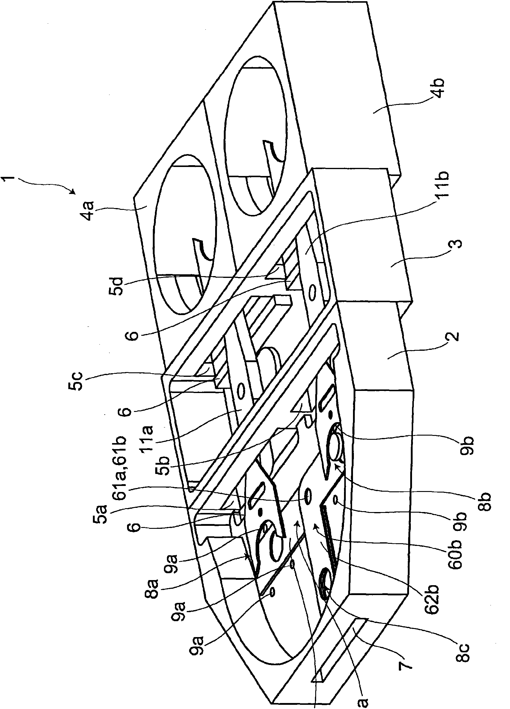
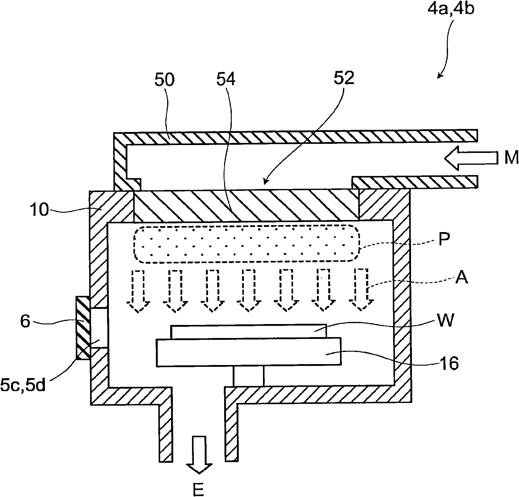
[0071] figure 1is a schematic cutaway perspective view showing a processing device according to an embodiment of the present invention. Such as figure 1 As shown, the processing apparatus 1 comprises a load lock chamber 2 adapted to reduce the pressure therein, a transfer chamber 3 and processing chambers 4a, 4b. multiple (in figure 1 Handover gates (handover gates) 5a to 5d at four locations in total in the view of , are formed in parallel in the walls between the load lock chamber 2 and the transfer chamber 3 and between the transfer chamber 3 and the processing chambers 4a, 4b. The load lock chamber 2 and the transfer chamber 3, and the transfer chamber 3 and the processing chambers 4a, 4b are connected by transfer gates 5a to 5d, allowing the internal spaces of the respective chambers to communicate with each other. Here, the tops of the load lock chamber 2, the transfer...


PUM


Abstract

A robot device for delivering and receiving an object by rotating a finger by a predetermined angle, the finger having holding means for holding the object. A first finger and second finger are arranged away from each other on a drive shaft of the robot device. The first finger has a first arm and second arm extending from the center of rotation of the first finger so as to be away from each other at a predetermined angle from each other. The second finger has a third arm and fourth arm extending from the center of rotation of the second finger arm so as to be away from each other at a predetermined angle from each other. When the first arm and third arm are superposed over each other in the direction of the axis of the drive shaft, the second arm and fourth arm are at positions away from each other. The robot can increase productivity without an increase in its size and its cost.

Description

technical field [0001] The invention relates to a robot device for conveying workpieces, a processing device provided with the robot device, an ashing system and an ashing method. Background technique [0002] For example, in a process for forming circuit patterns and the like on a workpiece such as a glass substrate for a liquid crystal display device and a wafer for a semiconductor device, various processing steps must be performed on the workpiece . Thus, a so-called multi-chamber system has been proposed in which a plurality of processing chambers are provided to perform processing in each chamber simultaneously or step by step. [0003] When processing workpieces in a multi-chamber system, the robotic device receives unprocessed workpieces from a supply unit and supplies the workpieces to a processing chamber. For example, after the workpiece has been processed in a processing chamber, the robotic device receives the workpiece from the processing chamber and transfers...

Claims


Application Information

Patent Timeline
Patent Type & Authority Applications(China)
IPC IPC(8): H01L21/677B25J9/06H01L21/3065
CPCB25J9/042H01L21/67069H01L21/67766H01L21/67742H01L21/67745H01L21/67196B25J9/106B25J11/0095B25J15/0052B25J9/0084
Inventor 东野秀史田部圣裕
Owner SHIBAURA MECHATRONICS CORP
Features
  • Generate Ideas
  • Intellectual Property
  • Life Sciences
  • Materials
  • Tech Scout
  • Unparalleled Data Quality
  • Higher Quality Content
  • 60% Fewer Hallucinations
Learn More