

Speed limit sensing and vehicle speed control device
A vehicle speed control and receiving device technology, applied in the direction of control devices, speed/acceleration control, measuring devices, etc., can solve problems affecting signal reception, etc., and achieve the effect of clear road information, accurate positioning, and accurate road speed limit information
- Summary
- Abstract
- Description
- Claims
- Application Information
AI Technical Summary
Problems solved by technology
Method used
Image

Examples
Embodiment Construction
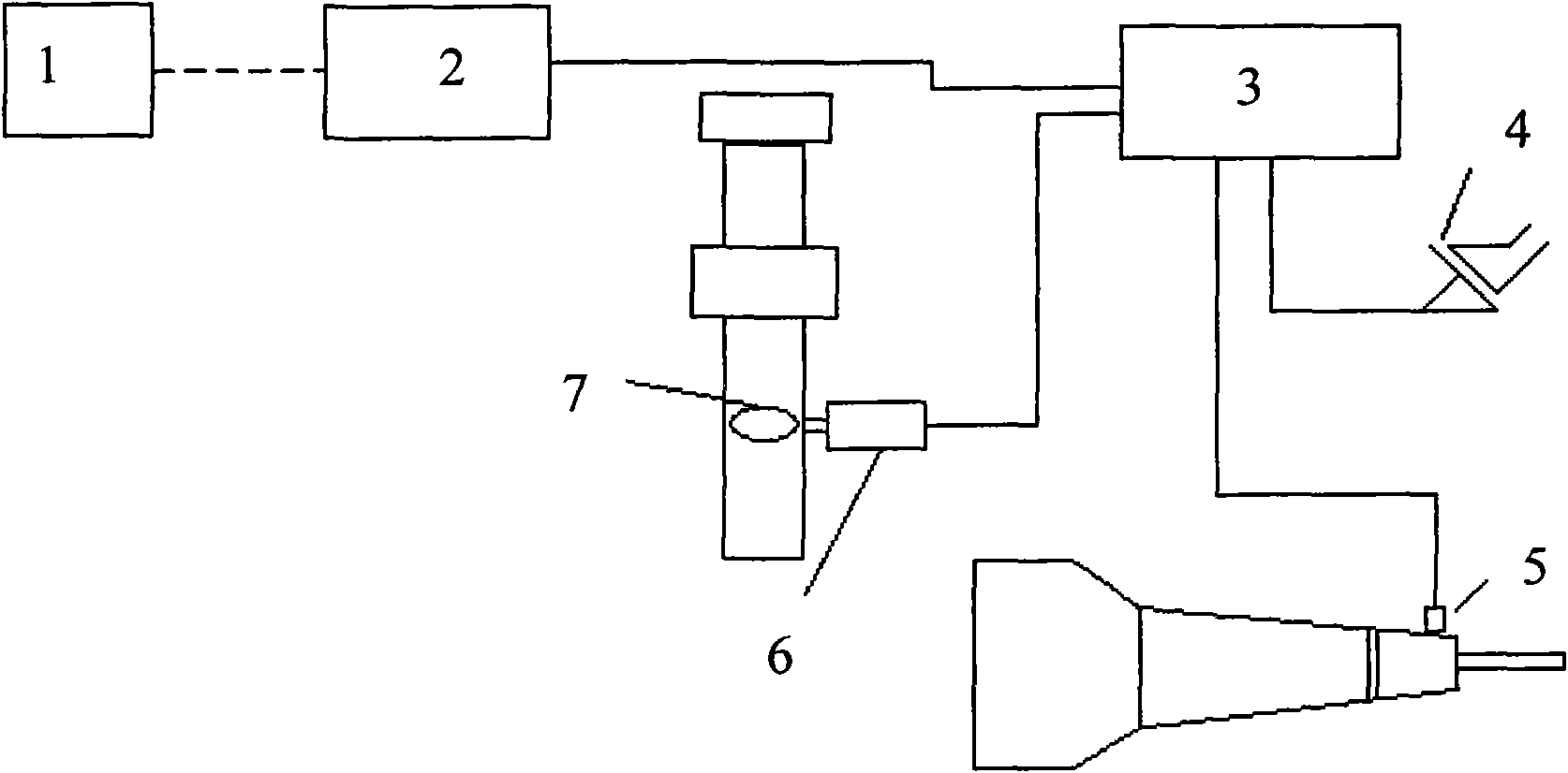
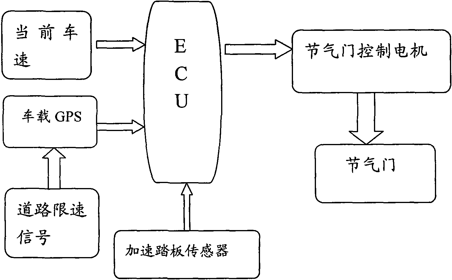
[0024] Such as figure 1 The shown device includes speed limit signal generation and vehicle receiving device, vehicle speed sensor, overspeed prompt and control device and ECU, signal generation and vehicle receiving device includes speed limit transmitter 1 and vehicle GPS 2, and speed limit transmitter 1 is installed in Speed sections, launch and edit GPS map signals with road speed limit information; overspeed prompts and control devices include throttle control motor 6 and accelerator pedal sensor 4; vehicle-mounted GPS2, vehicle speed sensor 5, throttle control motor 6 and accelerator pedal sensor 4 are all Connect to ECU3.
[0025] The vehicle speed sensor adopts Hall vehicle speed sensor, and its structure is mainly composed of ring gear, Hall element, permanent magnet and electronic circuit. The working principle is that the magnetic force lines of the permanent magnet pass through the Hall element and lead to the trigger ring gear. At this time, the ring gear is eq...
PUM
 Abstract
Description
Claims
Application Information