Angular momentum mechanism

An angular momentum, inertial body technology, applied in mechanical equipment, transmission, belt/chain/gear, etc., can solve the problems of application limitation, crank connecting rod mechanism cannot be applied to free piston engine, etc., and achieve simple structure and high efficiency. Effect

Inactive Publication Date: 2009-10-14
靳北彪
View PDF4 Cites 4 Cited by
  • Summary
  • Abstract
  • Description
  • Claims
  • Application Information

AI Technical Summary

Problems solved by technology

Although the crank-link mechanism is a mature and reliable mechanical mechanism that has been widely used for hundreds of years, it has two upper and lower dead points and considerable lateral force, and the torque at the dead point is zero, so it applications are limited
For example, the crank-and-rod mechanism cannot be applied to a free-piston engine

Method used


Image

  • Angular momentum mechanism
  • Angular momentum mechanism
  • Angular momentum mechanism

Examples


Embodiment Construction

[0038] Figure number

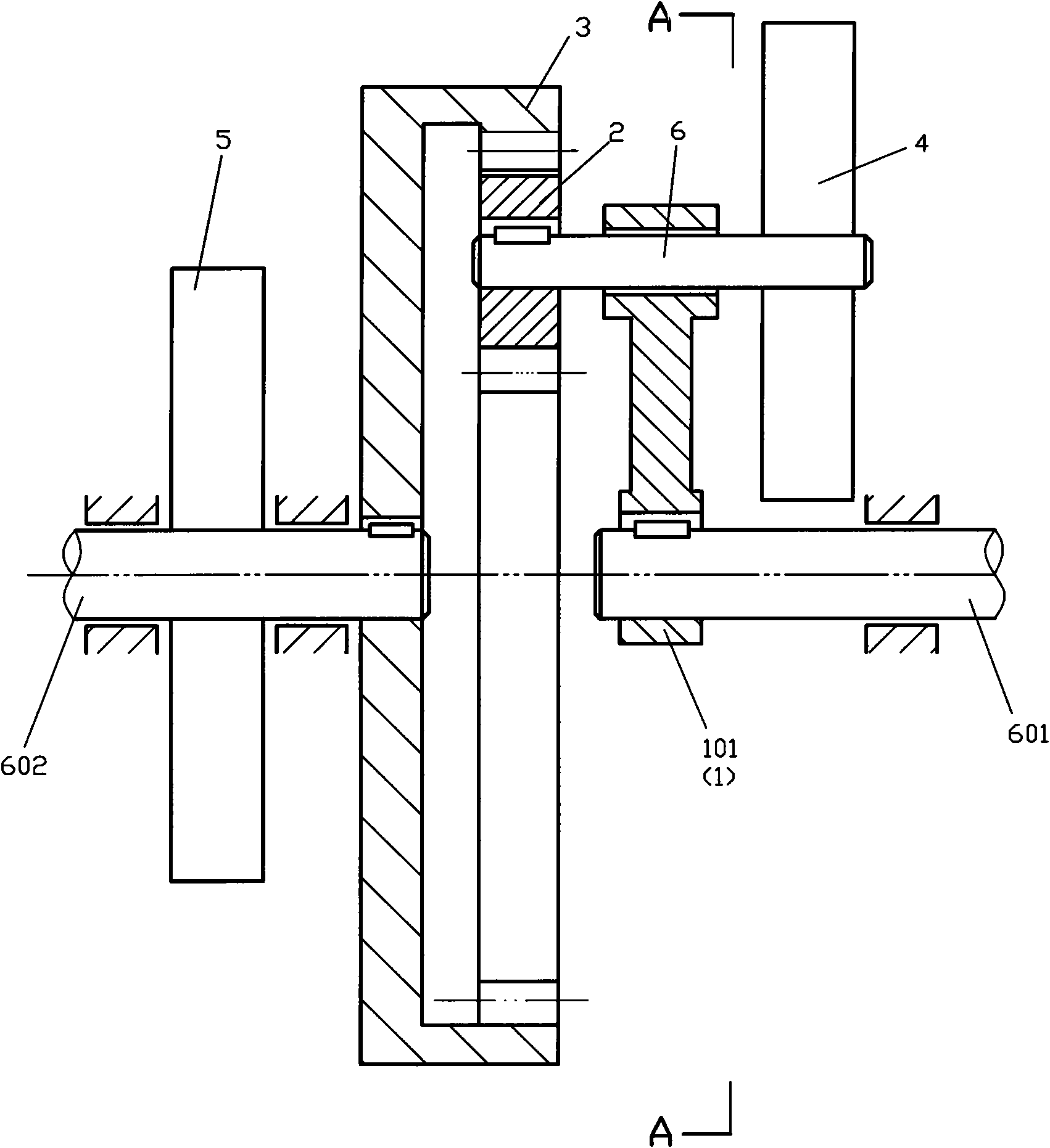
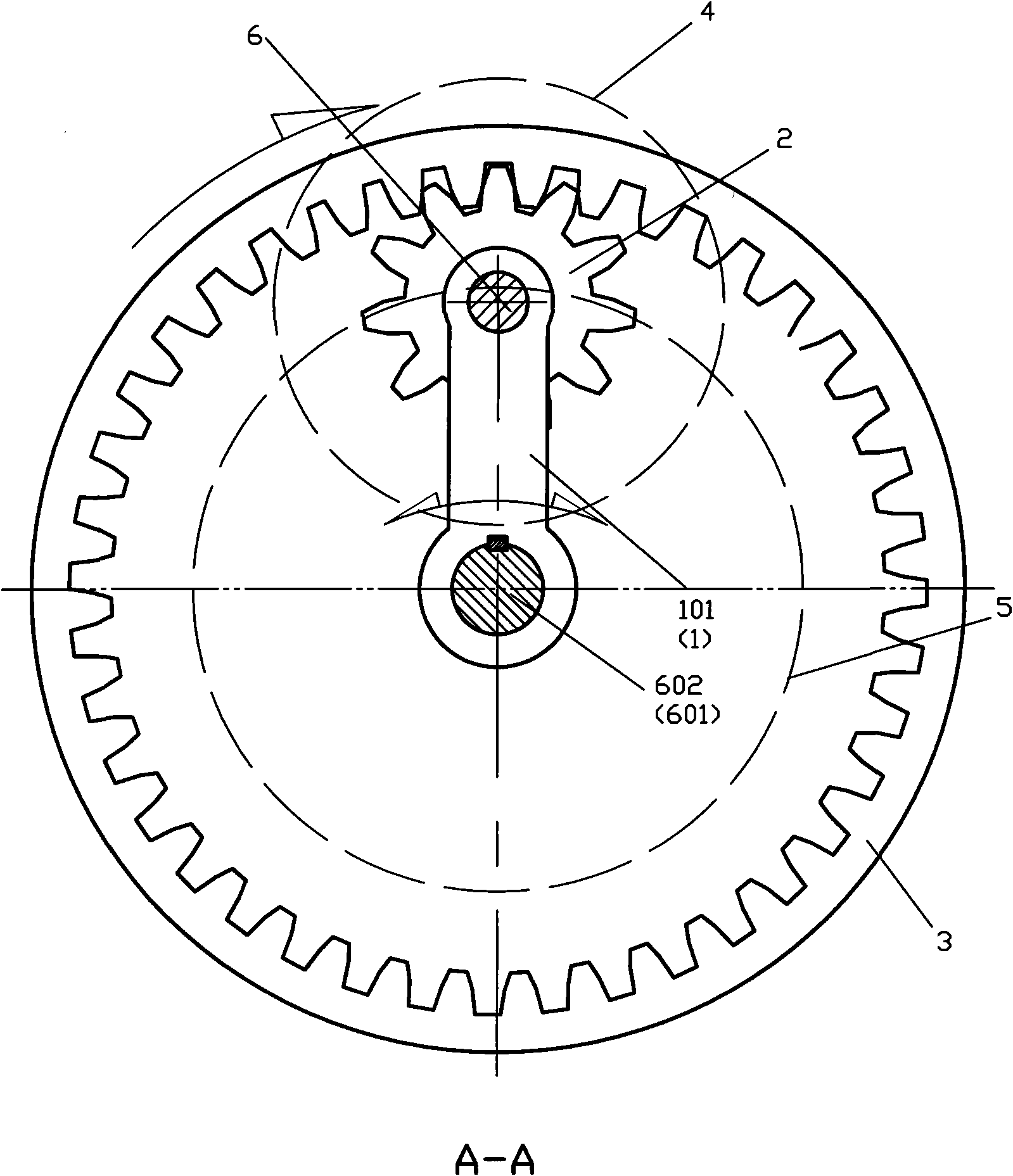
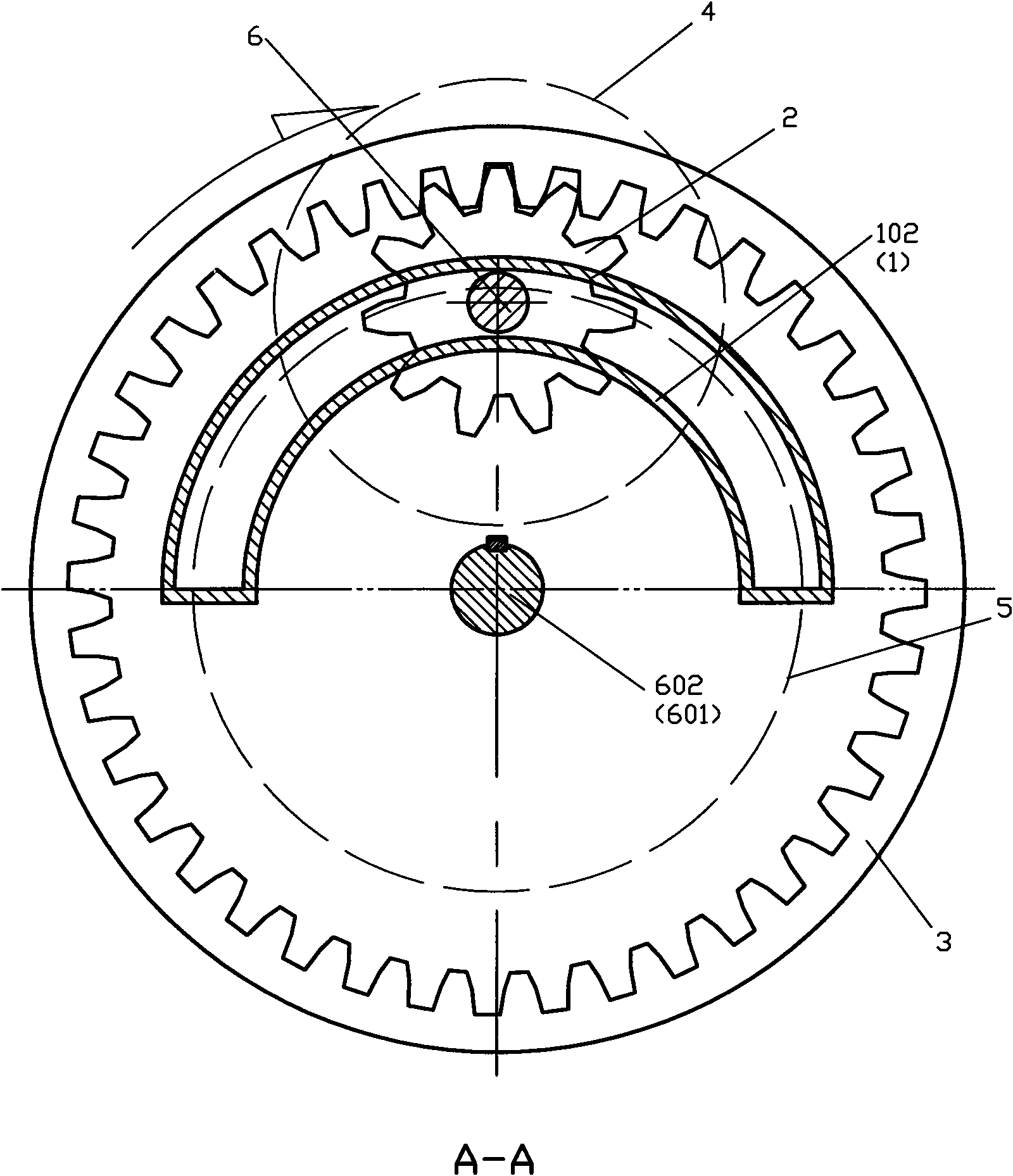
[0039] 1. Revolving structure 2. Planetary gear 3. Sun gear 4. Planetary rotary inertia body

[0040] 5. Center rotating inertia body 101. Revolving arm 102. Revolving arc guide rail 6. Planetary shaft

[0041] 601. Rotary power input shaft 602. Swing power output shaft 501. External gear inertia body

[0042] 502. Combined center rotary inertia body 401. Combined planetary rotary inertia body

[0043] 15. Inertial energy storage structure 16. Elastic body 17. Mass slider 18. Differential

[0044] 20. Planetary gear shaft 21. Planetary gear 22. Side gear A 24. Side gear B

[0045] The present invention is described in detail below in conjunction with accompanying drawing and specific embodiment:

[0046] Please refer to figure 1 , 2 , the angular momentum mechanism shown in 3, 4, 5, 6 and 7, comprising: a revolving structure 1, a planetary gear 2, a sun gear 3 and a planetary mass of inertia 4, characterized in that: the revolving structure 1 is set ...


PUM


Abstract

The invention discloses an angular momentum mechanism which comprises an orbital structural body, a planetary gear, a central gear and a planet rotating inertia body. The orbital structural body is provided with an orbital pivoting arm. The planetary gear is meshed with the central gear and the inertia thereof is connected to the planet rotating inertia body in a transferring manner. The planetary gear is provided with a planetary shaft which is fixedly connected with the planetary gear and is connected with the orbital pivoting arm in a rotating manner. When the planet rotating inertia body is arranged on the planetary shaft, the angular momentum mechanism is provided with or without a central rotating inertia body; and when the angular momentum is provided with the central rotating inertia body or the planet rotating inertia body is not arranged on the planetary shaft, the central rotating inertia body is connected with the central gear in a transferring manner. The angular momentum mechanism transforms the reciprocating or oscillating movement into rotary movement and has the advantages of high efficiency and simple structure.

Description

technical field [0001] The invention relates to the field of engines. Background technique [0002] To convert an oscillating power source or a reciprocating power source into a rotary power source, a crank linkage is usually used. Although the crank-link mechanism is a mature and reliable mechanical mechanism that has been widely used for hundreds of years, it has two upper and lower dead points and considerable lateral force, and the torque at the dead point is zero, so it application is restricted. For example, the crank-connecting rod mechanism cannot be applied in a free-piston engine. In order to convert the power of engines (such as free-piston and swing-piston engines) with swinging or reciprocating output power sources into rotary power output, the inventor proposed a rotary power engine with inertia (application number is 200810187999.X and 200820184153.6), but in order to further simplify the structure, improve performance, and expand the scope of use, the pres...

Claims


Application Information

Patent Timeline
Patent Type & Authority Applications(China)
IPC IPC(8): F16H37/12
Inventor 靳北彪
Owner 靳北彪
Why Eureka
Try Eureka