Draught fan control device and control method in power electronic power cabinet

A control device and control method technology, applied in pump control, mechanical equipment, machine/engine, etc., can solve problems such as heat dissipation structure changes, achieve improved heat dissipation, simple and effective control device structure, and simple and easy control methods

Active Publication Date: 2015-07-22
GLOBAL ENERGY INTERCONNECTION RES INST CO LTD +1
View PDF7 Cites 5 Cited by
  • Summary
  • Abstract
  • Description
  • Claims
  • Application Information

AI Technical Summary

Problems solved by technology

[0003] After the existing power cabinet design is completed, the internal power device setting position and power consumption are fixed, so the speed and airflow direction of the cooling fan can also be fixed at the initial design, but as the electronic devices After high integration and modularization become a trend, the location, quantity, power consumption, and even type of internal electrical components will be changed accordingly according to the demand, which leads to changes in the heat dissipation structure

Method used


Image

  • Draught fan control device and control method in power electronic power cabinet
  • Draught fan control device and control method in power electronic power cabinet

Examples


Embodiment Construction

[0049] The following will clearly and completely describe the technical solutions in the embodiments of the present invention with reference to the accompanying drawings in the embodiments of the present invention. Obviously, the described embodiments are only some, not all, embodiments of the present invention. Based on the embodiments of the present invention, all other embodiments obtained by persons of ordinary skill in the art without making creative efforts fall within the protection scope of the present invention.

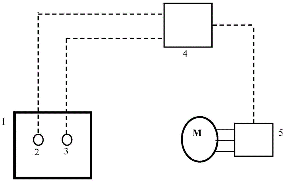
[0050] Such as figure 1 As shown, a fan control device in a power electronic power cabinet of the present invention includes a sensor unit, a fan controller 5 and a general controller 4;

[0051] The sensor unit is installed on the outer wall of the heating load box 1;

[0052] Fan controller 5 is connected with fan M;

[0053] Both the sensor unit and the fan controller 5 are connected with the general controller 4 .

[0054] Among them, the fan M is set i...


PUM


Abstract

The invention provides a draught fan control device and control method in a power electronic power cabinet. The draught fan control device comprises a sensor unit, a draught fan controller and a master controller. The control method is to determine the optimal operation mode through the measurement and the comparison of temperature and wind speed of a heat load case when the draught fan operates in the forward direction and the reverse direction. Compared with the prior art, the control device is simple and efficient in structure, interior structures of the draught fan and the power cabinet are not changed, meanwhile, the heat dissipation efficiency of the draught fan in the flexible power transmission and distribution converter valve power cabinet is improved, and the reliable operation of the power cabinet is guaranteed. The control method is simple and practicable, the rotation speed and the rotation direction of the draught fan are determined according to the heat dissipation condition of the load in the power cabinet, different heat dissipation schemes are provided for different power cabinets, the wide application of the power cabinet is achieved, meanwhile, the effective heat dissipation mode improves the service life and the operation efficiency of the power cabinet, the overheat phenomenon caused by the inverse connection of the circuit of the draught fan is prevented, and the operation reliability of the power cabinet is guaranteed.

Description

technical field [0001] The invention relates to the field of temperature control, in particular to a fan control device and control method in a power electronic power cabinet. Background technique [0002] The forced air convection inside the power cabinet and inside and outside the power cabinet is formed by the fan, which is the main means of cooling the power devices inside the power cabinet today. [0003] After the existing power cabinet design is completed, the internal power device setting position and power consumption are fixed, so the speed and airflow direction of the cooling fan can also be fixed at the initial design, but as the electronic devices After high integration and modularization become a trend, the location, quantity, power consumption, and even type of internal electrical components will be changed accordingly according to the needs, which leads to changes in the heat dissipation structure. Due to the change of heat dissipation structure, there is an...

Claims


Application Information

Patent Timeline
Patent Type & Authority Applications(China)
IPC IPC(8): F04D27/00
Inventor 胡晓乔尔敏
Owner GLOBAL ENERGY INTERCONNECTION RES INST CO LTD
Why Eureka
Try Eureka