Vibration damping device, method of controlling vibration damping device, method of correcting offset of vibration damping device, and leaf spring

A technology of vibration damping device and power device, which is applied in the direction of power device, jet propulsion device, internal combustion propulsion device, etc., can solve problems such as difficulty in effectively isolating low-frequency vibration and high-frequency vibration, hindering ride comfort, and inability to isolate vibration, etc. Achieve the effects of reduced amplitude, improved ride comfort, and high reliability

Inactive Publication Date: 2009-10-14
SINFONIA TECHNOLOGY CO LTD
View PDF12 Cites 8 Cited by
  • Summary
  • Abstract
  • Description
  • Claims
  • Application Information

AI Technical Summary

Problems solved by technology

[0022] (1) It is difficult to effectively isolate the low-frequency vibration during idling and the high-frequency vibration during high-speed driving in the devices with improved spring characteristics of the engine mount as shown in Patent Documents 1 and 2
[0023] (2) Moreover, in the device shown in Patent Document 3, which can selectively switch two spring constants by a switch to perform vibration damping, since the rotational speed of the engine is continuously changed from a low speed to a high speed, there is a possibility that the vibration cannot be isolated. In the area, body vibration is generated and transmitted to passengers through the floor, which hinders ride comfort

Method used


Image

  • Vibration damping device, method of controlling vibration damping device, method of correcting offset of vibration damping device, and leaf spring
  • Vibration damping device, method of controlling vibration damping device, method of correcting offset of vibration damping device, and leaf spring
  • Vibration damping device, method of controlling vibration damping device, method of correcting offset of vibration damping device, and leaf spring

Examples


Embodiment Construction

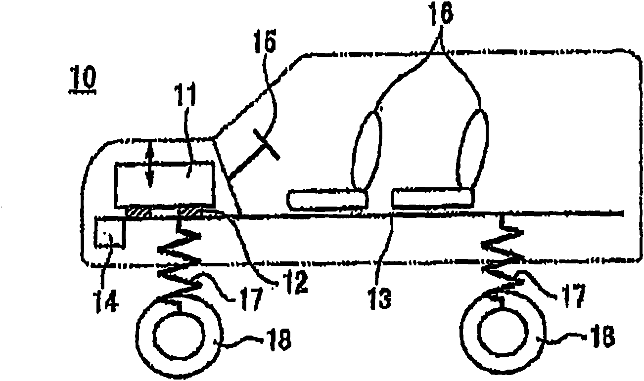
[0103] The best mode for implementing the automobile vibration damping device of the present invention will be described with reference to the accompanying drawings. figure 1 It is a schematic diagram showing an example of a vehicle body to which the automobile vibration damping device of the present invention is mounted.

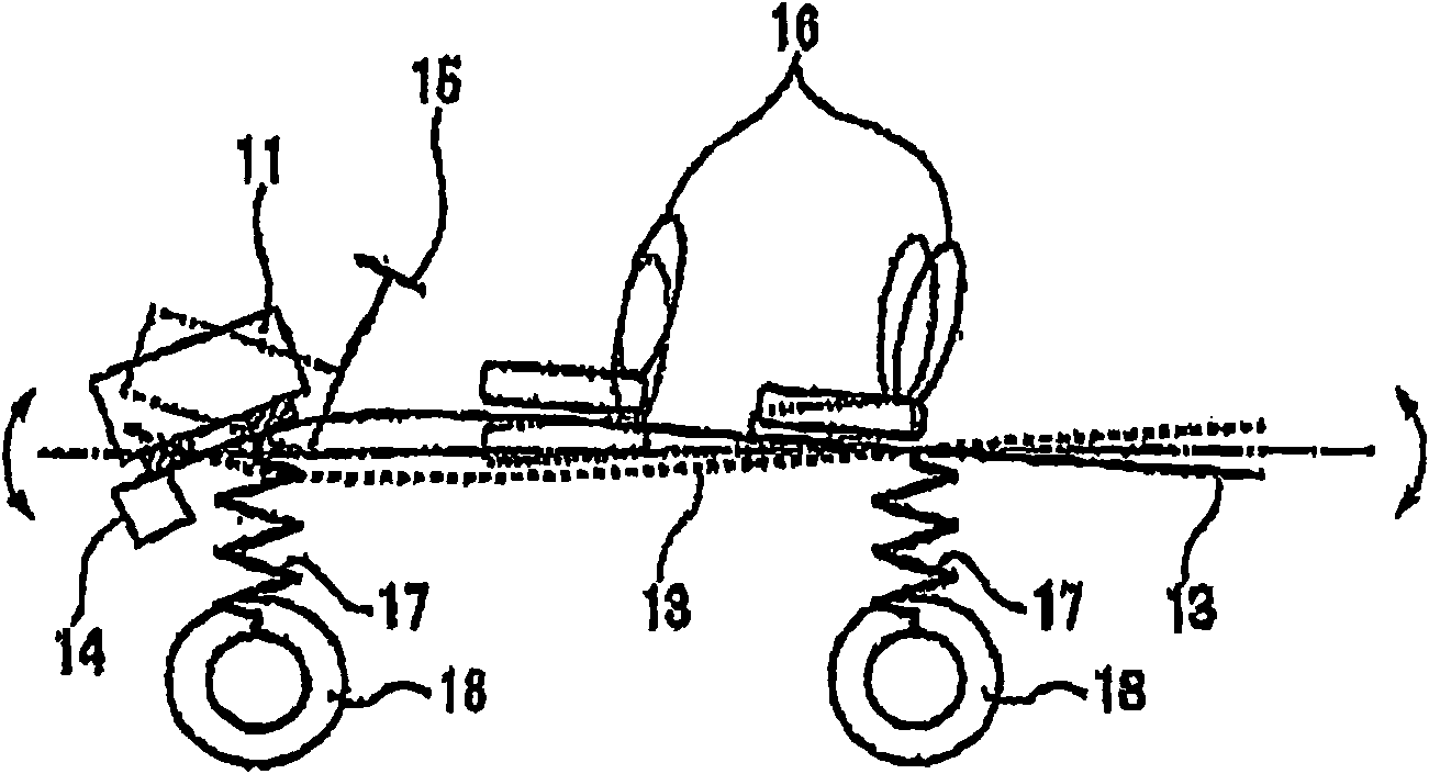
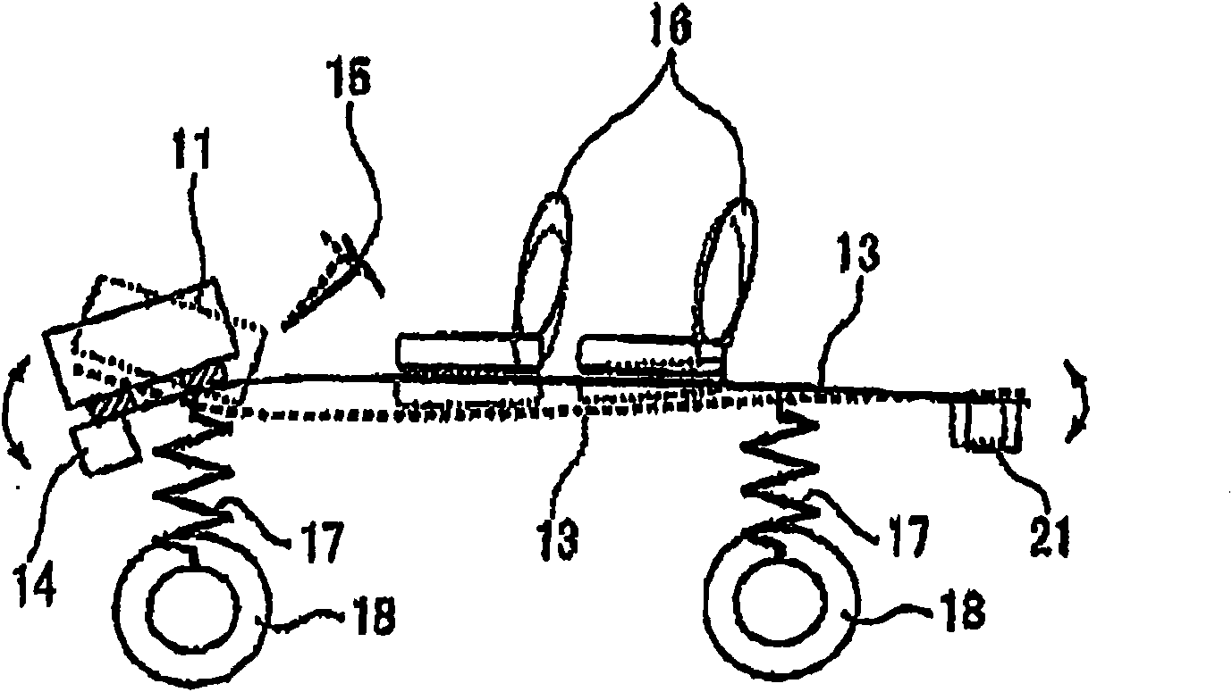
[0104] Here, the vehicle vibration damping device 10 is formed by combining an engine and a transmission, etc., with a power unit 11 that is supported on a vehicle body 13 by an engine bracket 12 for the purpose of isolating vibrations. The vibrating member 14 vibrates. Furthermore, a steering wheel 15 and a seat portion 16 are attached to the vehicle body 13 . Furthermore, the vehicle body 13 is supported by tires 18 via a suspension system 17 .

[0105] The vibrating member 14 used in this embodiment is directly fixed to the vehicle body 13 at a position different from the engine without the engine mount 12 . Furthermore, a linear actuator, a reciproc...


PUM


Abstract

The invention provides a vibration damping device, a method of controlling the vibration damping device, a method of correcting offect of the vibration damping device and a leaf spring. The vibration damping device for an automobile, in which a power plant constructed from an engine and a transmission that are joined to each other is supported on a vehicle body through engine mounts in order to isolate vibration. The vibration damping device has vibration exciting means for generating vibration different from that of the engine, so that the amplitude of vibration of a seat etc. can be reduced by reaction force of the vibration exciting means. When the mode of vibration of the vehicle body is adjusted so as to have a node of the vibration near the seat, the amplitude of vibration of the vehicle body near the seat is reduced to improve ride comfort of the automobile.

Description

technical field [0001] The present invention relates to an automobile vibration damping device capable of reducing vibration amplitudes of a seat portion and a steering wheel portion in an engine-mounted vehicle such as an automobile to improve riding comfort. [0002] Furthermore, the present invention relates to a vibration damping device and a control method of the vibration damping device for suppressing vibration of a vibration damping target device such as an automobile. [0003] Furthermore, the present invention relates to an offset correction method of a vibration damping device. [0004] Furthermore, the invention relates to a leaf spring provided on a linear actuator. [0005] This application is based on Japanese Patent Application No. 2006-329495 filed in Japan on December 6, 2006, Japanese Patent Application No. 2006-329497 filed in Japan on December 6, 2006, and Japanese Patent Application No. 2007 filed in Japan on April 5, 2007. -99468, Japanese Patent Appli...

Claims


Application Information

Patent Timeline
Patent Type & Authority Applications(China)
IPC IPC(8): B60K5/12B62D37/04F16F15/02
Inventor 村岸恭次藤井隆良福永崇守屋英朗中野克好中川洋尾上孝志佐藤雄志
Owner SINFONIA TECHNOLOGY CO LTD
Why Eureka
Try Eureka