Fire coal smoke rotary atomization dedusting and desulfurization device

A technology for coal-fired flue gas and desulfurization devices, which is applied in the directions of dispersed particle separation, chemical instruments and methods, separation methods, etc., can solve the problems of large droplet surface area, high cost, clogging of sieve plate holes, etc.

Inactive Publication Date: 2009-10-21
徐彬 +1
View PDF0 Cites 6 Cited by
  • Summary
  • Abstract
  • Description
  • Claims
  • Application Information

AI Technical Summary

Problems solved by technology

If sodium hydroxide is used for the desulfurization liquid of this dust removal and desulfurization method, there are the following deficiencies: 1. After the desulfurization slurry flows through the sieve plate holes, it forms a spray column composed of multiple groups of desulfurization slurry uninterrupted water flow, resulting in two sieve plate holes Blind zone formed between desulfurization slurry
At the same time, due to the uninterrupted water flow, the droplet surface area of ​​the spray column is too large, so it cannot fully react with the sulfur components in the desulfurized and dust-removed flue gas, resulting in poor desulfurization effect.
2. Since the desulfurization liquid is sodium hydroxide, the discharge of the desulfurization liquid produces secondary pollution
If the desulfurization liquid adopts lime or limestone, it has the following disadvantages: 1. It still has the defect that the above-mentioned desulfurization slurry cannot fully react with the sulfur components in the desulfurized and dust-removed fl

Method used


Image

  • Fire coal smoke rotary atomization dedusting and desulfurization device
  • Fire coal smoke rotary atomization dedusting and desulfurization device
  • Fire coal smoke rotary atomization dedusting and desulfurization device

Examples


Embodiment Construction

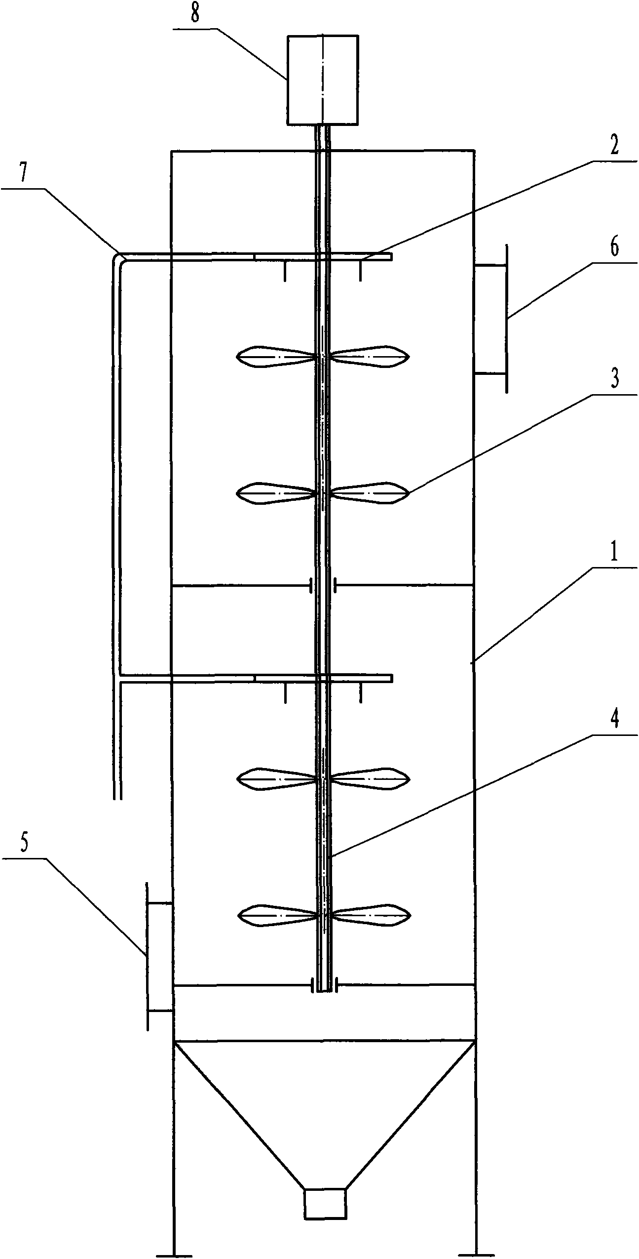
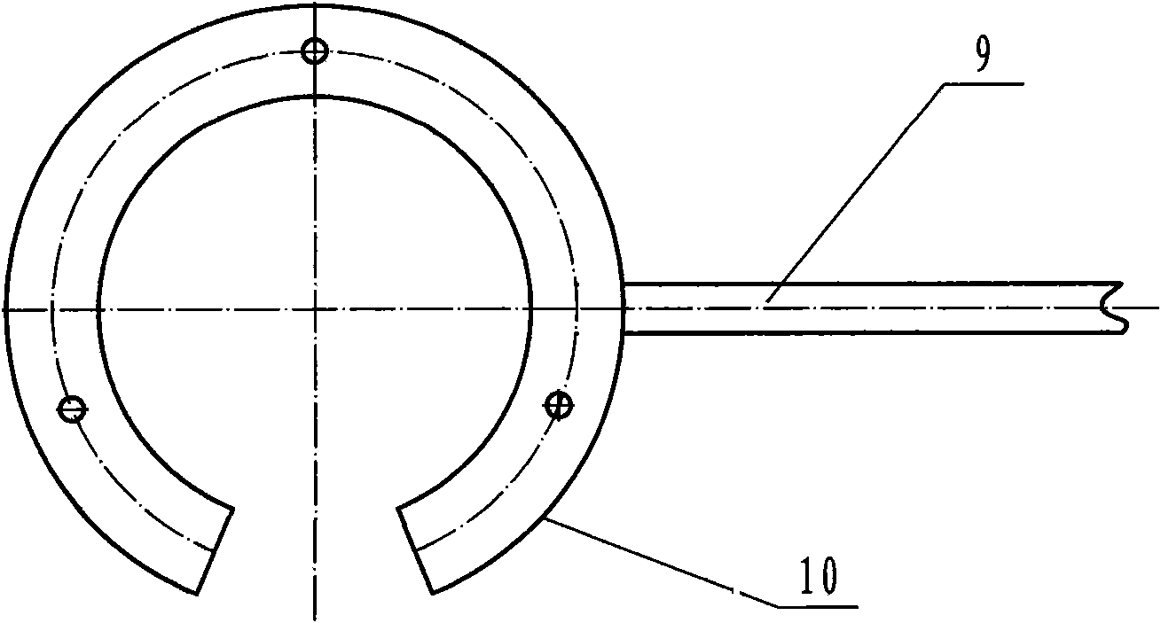
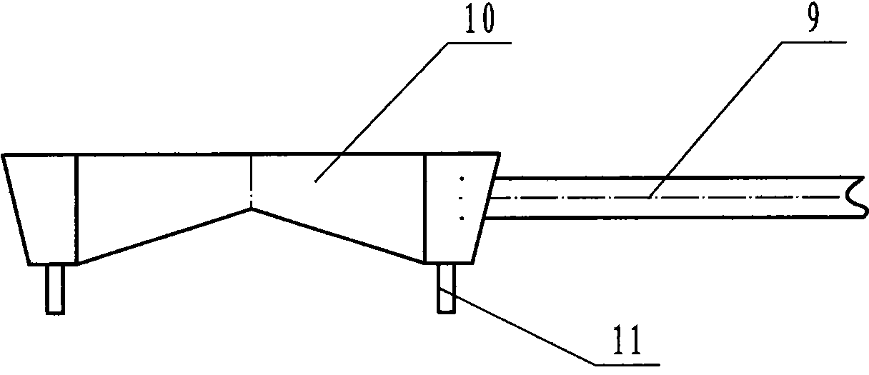
[0019] Below with accompanying drawing as embodiment the present invention is further described: as figure 1 As shown, the coal-burning smoke cyclone mist desulfurization and dust removal device includes a desulfurization tower body 1, an input pipe 7 arranged on the wall of the tower body 1 for transporting desulfurization slurry, and input and output ports 5, 6 for desulfurized and dust-removed gas, A desulfurization and dedusting atomizer is provided in the tower body 1. The desulfurization and dedusting atomizer is composed of a spraying plate 2 and a liquid swirling fan 3 matched with the spraying plate 2. The spraying plate 2 is connected with the input of the desulfurization slurry. The pipe 7 is connected, and the liquid spinning fan 3 is assembled on the lower part of the corresponding spraying disc 2. The spraying disc 2, the liquid spinning fan 3 and the inner wall of the desulfurization tower body 1 form a swirling flow chamber for the mixed reaction of the desulfur...


PUM


Abstract

The invention provides a fire coal smoke rotary atomization dedusting and desulfurization device, which comprises a desulfurization tower body, and an input pipe used for conveying desulfurizing slurry and an input and output port for desulfurized and dedusted gas; the input pipe and the input and output port are arranged on the wall of the tower body; a desulfurization and dedusting atomizer is arranged in the tower body and consists of a slurry spraying disk and a liquid rotating fan matched with the slurry spraying disk; the slurry spraying disk is communicated with the input pipe for conveying the desulfurizing slurry; the liquid rotating fan is assembled on a lower part or an upper part corresponding to the slurry spraying disk; and the slurry spraying disk, the liquid rotating fan, and the inner wall of the desulfurization tower body form a rotational flow chamber for hybrid reaction of the desulferizaition slurry and the desulfurized and dedusted gas. The device adopts atomization dedusting and desulfurization, has the desulfurization efficiency reaching over 95 percent, and can reduce the whole manufacturing cost of a desulfurization system by 70 percent and energy consumption by between 30 and 40 percent. At the same time, the device has simple whole structure, small volume, and flexible and convenient application; and according to requirements of different users, desulfurization and dedusting atomizers can be serially connected in multiple stages for use, and a plurality of groups of the devices also can be serially connected for use.

Description

technical field [0001] The invention belongs to a wet dust removal and desulfurization device, in particular to a dust removal and desulfurization device for coal-fired smoke cyclone mist removal. Background technique [0002] At present, there are mainly four types of devices used for dust removal and desulfurization. One is the sieve plate type dust removal and desulfurization device. The input and output port and the funnel-shaped sieve plate assembled in the tower body. The structures of the other three dedusting and desulfurizing devices are basically the same as the above-mentioned sieve plate type dedusting and desulfurizing devices, the main difference being that the desulfurizing slurry spraying device adopts a different structure. The dust removal and desulfurization process of the sieve plate type dust removal and desulfurization device is as follows: the desulfurization slurry is input into the funnel from the input port, and is sprayed out through the sieve hol...

Claims


Application Information

Patent Timeline
IPC IPC(8): B01D53/48B01D53/78
Inventor 徐彬张润春
Owner 徐彬
Why Eureka
Try Eureka