Ultrasonic metal surface machining cutter

A technology for metal surface and processing tools, which is applied in the direction of metal processing equipment, manufacturing tools, and tools for lathes, etc., and can solve the problem that the surface of parts cannot be processed.

Active Publication Date: 2013-03-20
SHANDONG HUAWIN ELECTRICAL & MECHANICAL TECH
View PDF0 Cites 0 Cited by
  • Summary
  • Abstract
  • Description
  • Claims
  • Application Information

AI Technical Summary

Problems solved by technology

[0003] The technical task of the present invention is to provide an ultrasonic metal surface processing tool in order to overcome the deficiency that the existing ultrasonic metal surface processing tool cannot process the surface of the rotating body part with a smaller distance to the step root.

Method used


Image

  • Ultrasonic metal surface machining cutter
  • Ultrasonic metal surface machining cutter

Examples


Embodiment Construction

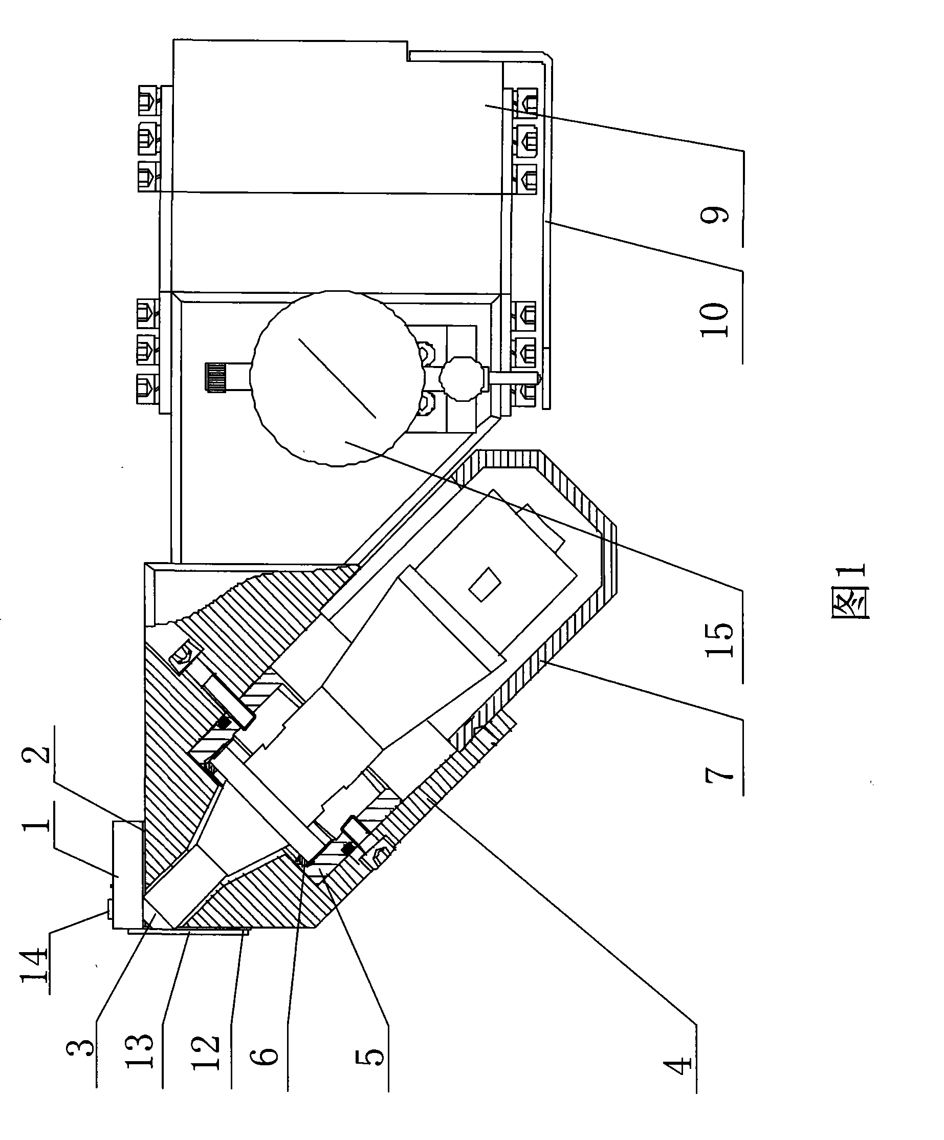
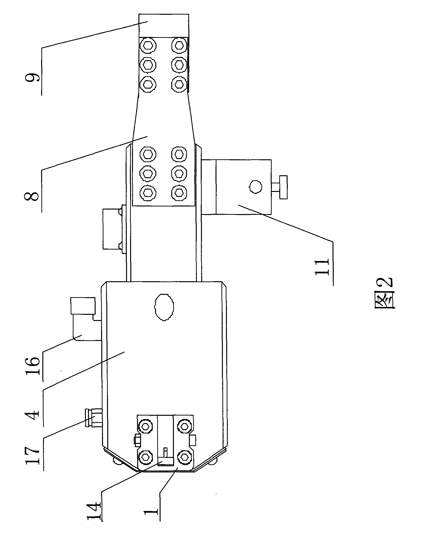
[0021] Attached below figure 1 , 2 The ultrasonic metal surface machining tool of the present invention will be described in detail below.

[0022] as attached figure 1 , 2 As shown, the ultrasonic metal surface processing tool of the present invention has a structure including a tool head 1, a tool seat adjustment pad 2, a horn 3, a horn seat 4, a steel sleeve 5, a horn adjustment pad 6, and a rear end cover 7. Shrapnel 8, briquetting block 9, dial indicator baffle 10, dial indicator seat 11, oil baffle 12, oil baffle support 13, tool head 14 and dial indicator 15, tool head 1 is prior art, The tool head 1 is set on the horn seat 4 through the tool seat adjustment pad 2, the tool head 14 is arranged on the tool head 1, the steel sleeve 5 is fixed in the hole of the horn seat 4 by bolts, and the horn 3 is set on the The horn base 4 is in contact with the inner surface of the steel sleeve 5, the horn 3 and the steel sleeve 5 are adjusted through the horn adjustment pad 6 to...


PUM


Abstract

The invention provides an ultrasonic metal surface machining cutter. The structure of the cutter comprises a cutter head, an amplitude transformer, an amplitude transformer seat, an elastic slice, a pressing block, an oil baffle plate and a pressure or displacement display device. The amplitude transformer is arranged inside the amplitude transformer seat which is connected with the pressing block by the elastic slice, and the amplitude transformer seat is provided with the pressure or displacement display device. The cutter has the following innovations: (1) the contact part between a small end of the amplitude transformer and the tool head is made into conical surface, bevel surface or sphere so as to cause ultrasonic energy output to form a certain angle, thus being capable of machining parts which can not be machined by an ordinary ultrasonic surface machining device; (2) the cutter head is positioned on the amplitude transformer seat by a tool seat adjusting pad; (3) the amplitude transformer seat is internally provided with an oil inlet passage and an oil return passage; and (4) the amplitude transformer seat at the contact part between the small end of the amplitude transformer and the tool head is provided with the oil baffle plate. Compared with the prior art, the ultrasonic metal surface machining cutter can perform ultrasonic machining on revolving body stepped surface with smaller step root distance and size, can machine smaller inner bores, and can perform ultrasonic machining on a plurality of machine tools such as vertical lathes, horizontal lathes, boring lathes and the like in a matching way.

Description

(1) Technical field [0001] The invention relates to a device capable of reducing the surface roughness of the inner hole, outer circle and end surface of a revolving body part, especially the surface of a revolving body part that can process large steps or counterbores and requires a smaller distance from the step root of the part Ultrasonic metal surface machining tools with reduced roughness values. (2) Technical background [0002] At present, the existing ultrasonic metal surface processing tools work by connecting the tool body and the tool head together through threads. The tool head and the tool body are concentrically matched, the working part of the tool head is close to the center of the tool body, and the diameter of the tool body is more than twice the diameter of the tool head, and the size of the tool head protruding from the tool body is limited. The surface of the step-shaped rotary part with a small distance requirement cannot be processed; the smaller inne...

Claims


Application Information

Patent Timeline
Patent Type & Authority Patents(China)
IPC IPC(8): B23B37/00B23B27/00
Inventor 王爱福
Owner SHANDONG HUAWIN ELECTRICAL & MECHANICAL TECH
Why Eureka
Try Eureka