Automobile braking system based on wire control

An automobile braking system and braking system technology, applied in the field of automobile braking systems, can solve problems such as inconvenient installation, complex structure, and failure to be monitored in real time

Active Publication Date: 2012-11-28
CHERY AUTOMOBILE CO LTD
View PDF4 Cites 0 Cited by
  • Summary
  • Abstract
  • Description
  • Claims
  • Application Information

AI Technical Summary

Problems solved by technology

However, no matter the traditional hydraulic brake or the above-mentioned technologies, there are defects such as complex structure, inconvenient installation, high price, and failure to be monitored in real time. Description of braking effect

Method used


Image

  • Automobile braking system based on wire control
  • Automobile braking system based on wire control
  • Automobile braking system based on wire control

Examples


Embodiment Construction

[0012] Automobile brake system of the present invention comprises following mechanism:

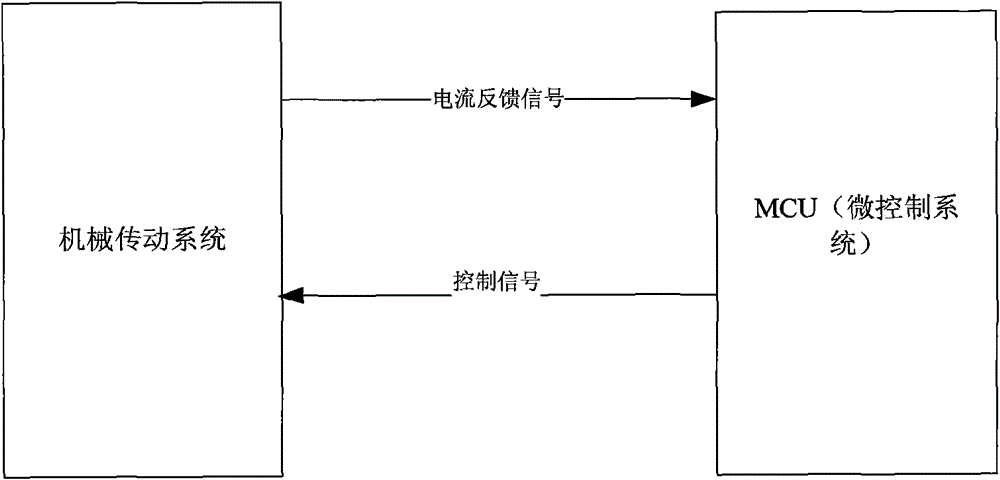
[0013] Microcontroller system (MCU), such as figure 1 As shown, the micro-control system (MCU) collects various signals and obtains the feedback signal of the motor current, and outputs control signals to the mechanical transmission system through the micro-control system (MCU) to control the action process of the mechanical transmission system.

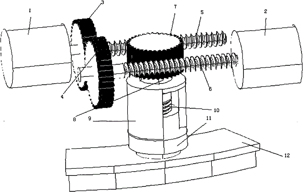
[0014] Drive motor 1 and drive motor 2 are fixedly connected with screw mandrel 5 and screw mandrel 6 respectively, as figure 2 shown. During the running of the vehicle, the drive motors 1 and 2 receive control signals from the embedded control system at any time.

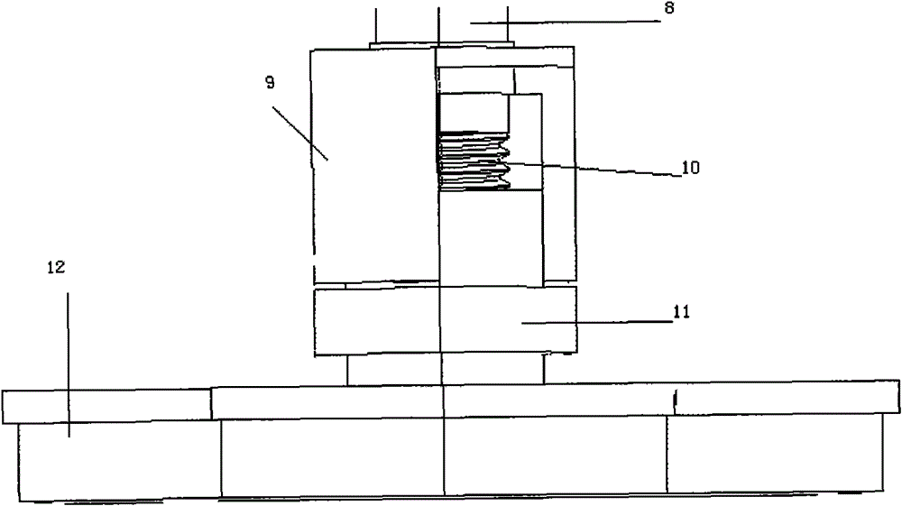
[0015] The gear 3 and the gear 4 are respectively fixed on the screw rod 5 and the screw rod 6 and engage with each other, wherein the screw rod 5 and the screw rod 6 are jointly engaged with the shaft gear 7 front and rear, and the shaft gear 7 is fixed on the brake shaft 8 . Wh...


PUM


Abstract

The invention discloses an automobile braking system based on wire control, which comprises a mechanical transmission mechanism and a brake pushrod group mechanism, wherein the mechanical transmissionmechanism comprises two drive motors (1, 2), two screw mandrels (5, 6) and a shaft lever gear (7). Two drive motors are fixedly connected with the two screw mandrels respectively, and the two screw mandrels are meshed with the shaft lever gear (7); the brake pushrod group mechanism comprises a brake shaft lever (8), a brake nut (11) and a brake block (12), and the shaft lever gear (7) is fixed onthe brake shaft lever. A screw thread (10) is arranged at one end of the brake shaft lever (8) near the brake block (12) and the brake shaft lever (8) is sheathed to the brake nut (11) by the screw thread (10). The automobile braking system has simple structure, casts off the traditional hydraulic control and represents the convenience of operation in respect of installation and maintenance. Furthermore, the braking system has good universality and is suitable for all automobile types in principle, in particular for automobiles using new energy, thus being capable of realizing pure electric automobiles in the true sense.

Description

technical field [0001] The invention relates to an automobile braking system, in particular to an automobile braking system based on wire control. Background technique [0002] At present, most vehicle brake systems at home and abroad are still based on hydraulically controlled mechanical pressure to achieve the purpose of braking. Traditional brake systems have long gas or liquid transmission pipelines and many valve components. For long-wheelbase or multi-axle vehicles and remote Distance control vehicles are prone to brake hysteresis. In the known technology, technical materials similar to the technical effect of the present invention are: "linear braking type" braking system (CN101039826), as disclosed in it, under the linear working state, brake is produced by pedal pressure simulator The displacement is processed by the corresponding electronic control unit to obtain the output braking torque. Through this technology, we can realize that the braking signal is collect...

Claims


Application Information

Patent Timeline
Patent Type & Authority Patents(China)
IPC IPC(8): B60T13/74B60T8/17
Inventor 朱得亚胡滨周勇
Owner CHERY AUTOMOBILE CO LTD
Why Eureka
Try Eureka