Yarn extraction nozzle

A yarn and nozzle seat technology, applied in the field of yarn extraction nozzles, can solve the problems of nozzle insert wear, high stress, etc., and achieve the effects of reduced wear, high hardness, and high light transmission

Inactive Publication Date: 2009-10-21
SAURER GERMANY GMBH & CO KG
View PDF1 Cites 2 Cited by
  • Summary
  • Abstract
  • Description
  • Claims
  • Application Information

AI Technical Summary

Problems solved by technology

Although the wear resistance of the yarn withdrawal nozzle can be improved by using uncolored ceramics, the basic problem of such yarn withdrawal nozzles cannot be overcome even by means of a nozzle insert made of uncolored ceramics, that is, in the The yarn withdrawn during the spinning run puts high stress on the nozzle insert, which at the same time wears out rather quickly

Method used


Image

  • Yarn extraction nozzle
  • Yarn extraction nozzle
  • Yarn extraction nozzle

Examples


Embodiment Construction

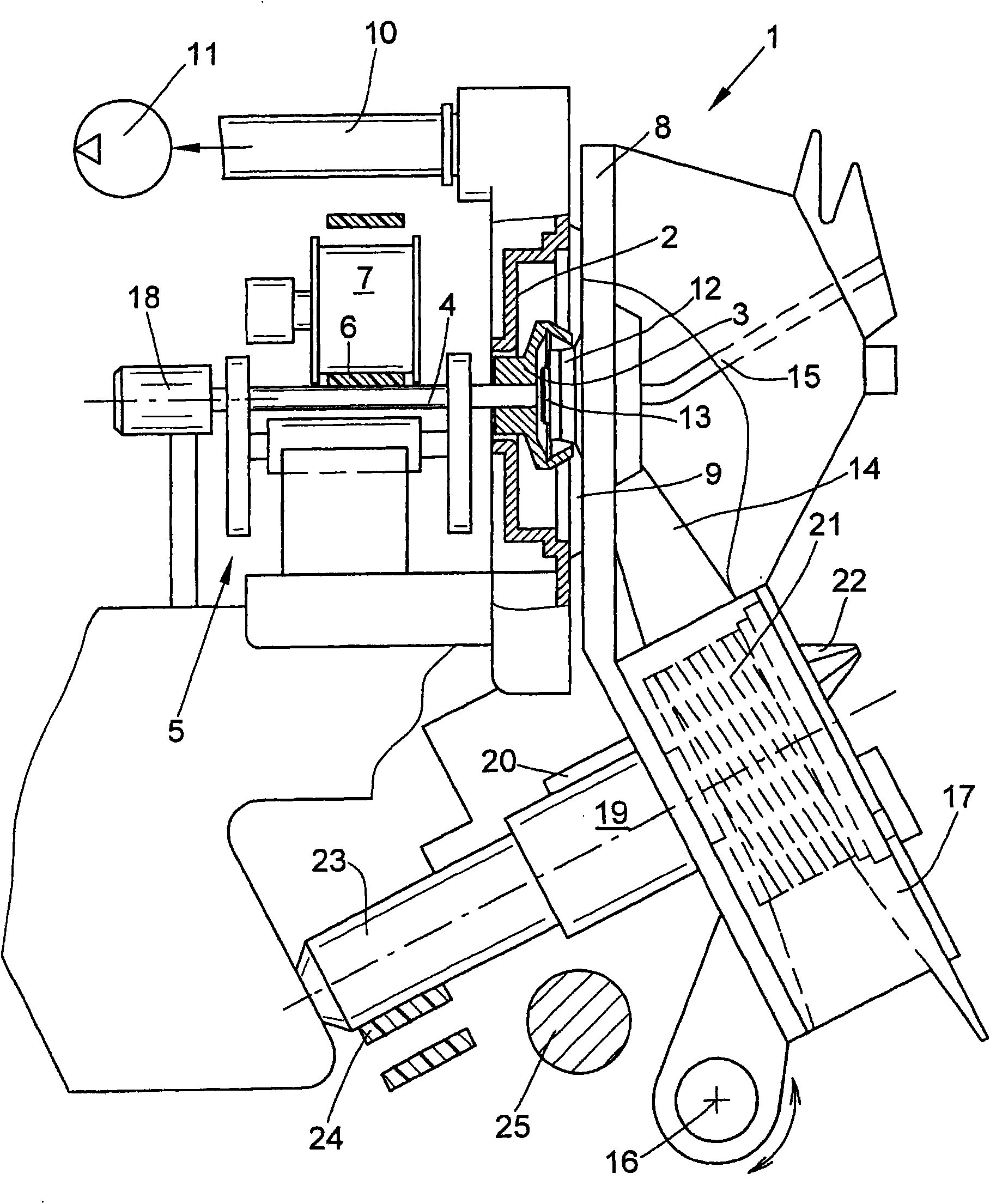
[0023] figure 1 An open-end rotor spinning device 1 is shown schematically. As is known, such open-end spinning devices 1 each have a rotor housing 2 in which a spinning cup of a spinning rotor 3 rotates at a high rotational speed. Here, the spinning rotor 3 is supported, for example, by its rotor shaft 4 in the bearing recess of a so-called support disc bearing structure 5 and is driven in a frictional engagement via a tangential belt 6 along the machine length. 3. The tangential belt 6 is driven by the pinch roller 7. The axial fixation of the rotor shaft 4 is achieved, for example, by means of a permanent-magnet axial bearing 18 .

[0024] The rotor housing 2 , which is open to the front, is closed during spinning operation by a pivotally mounted cover 8 , into which a channel plate is inserted, which is attached to the rotor housing 2 by means of a peripheral sealing lip 9 superior. Furthermore, the rotor housing 2 is connected via a corresponding vacuum line 10 to a v...


PUM


Abstract

The present invention relates to a yarn extraction nozzle of a free end rotor spinning device, comprising a nozzle base and a optically distinguished mark, which is used for distinguishing type of the yarn extraction nozzle, a nozzle insert made of ceramic is fixed on the nozzle base. According to the invention, the nozzle insert (38) is made of transparent sub-micron ceramic.

Description

technical field [0001] The invention relates to a yarn withdrawal nozzle for an open-end rotor spinning device according to the preamble to the first aspect. Background technique [0002] Various embodiments of yarn withdrawal nozzles for open-end rotor spinning devices have been known for a long time and have been described in detail in a large number of patent documents. [0003] A common problem in open-end rotor spinning devices is that the actual yarn twist initiated by the rotation of the spinning rotor depending on various yarn parameters (such as yarn material) cannot be uniformly imparted to the produced yarn in line. Since too low a yarn twist in the yarn section between the rotor groove and the yarn withdrawal nozzle has a very negative influence on the spinning stability of the open-end rotor spinning device, a large number of different yarn withdrawal nozzles, which differ especially in the way the surface structure is constructed in the yarn feed region of th...

Claims


Application Information

Patent Timeline
Patent Type & Authority Applications(China)
IPC IPC(8): D01H4/40D01H4/08
CPCD01H4/40
Inventor 延斯·吉里格斯埃克哈德·松塔格
Owner SAURER GERMANY GMBH & CO KG
Why Eureka
Try Eureka