
Applications-oriented control device of speed-regulating clutch and control method thereof

A control device and clutch technology, applied in the direction of clutches, mechanical equipment, etc., can solve the problem of not meeting the needs of speed regulation and control in various applications, the poor matching ability of electro-hydraulic proportional servo valve characteristics, the core - electric control Insufficient hardware performance and other problems, to achieve the effect of avoiding speed fluctuation and oscillation, sensitive speed control, and small overshoot

Active Publication Date: 2009-10-21
SHANGHAI QIYAO HEAVY IND CO LTD
View PDF0 Cites 14 Cited by
  • Summary
  • Abstract
  • Description
  • Claims
  • Application Information

AI Technical Summary

Problems solved by technology

[0004] 1. The core of the control system - the hardware performance of the electronic controller is insufficient, and the control algorithm is not advanced enough
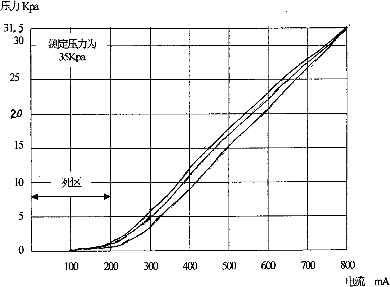
[0005] 2. Poor matching ability with the characteristics of the electro-hydraulic proportional servo valve
[0007] 3. It cannot well meet the speed regulation control needs of various applications

Method used


Image

  • Applications-oriented control device of speed-regulating clutch and control method thereof
  • Applications-oriented control device of speed-regulating clutch and control method thereof
  • Applications-oriented control device of speed-regulating clutch and control method thereof

Examples


Embodiment Construction

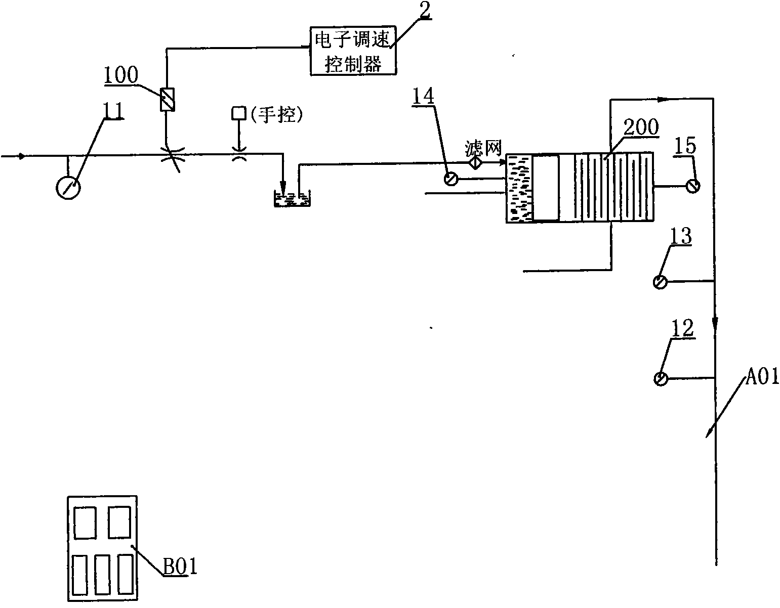
[0043] see figure 2 , which is a structural schematic diagram of an embodiment of the present invention applied to a hydraulic circuit (only a part of the circuit is shown in the figure) for controlling the fluid-viscous clutch. The speed regulating clutch control device for various applications of the present invention includes: a sensor unit 1, and an electronic speed regulating controller 2 electrically connected with the sensor unit. The sensor 1 includes: a control oil pressure sensor 11 arranged on the hydraulic circuit A01 and located in the control oil circuit of the viscous governor clutch, and a lubricating oil pressure sensor arranged on the hydraulic circuit and located in the cooling oil circuit of the viscous governor clutch 12 and lubricating oil temperature sensor 13; the input shaft sensor 14 that is connected with the input shaft of fluid viscous speed regulating clutch and the output shaft sensor 15 that is connected with the output shaft of liquid viscous ...


PUM


Abstract

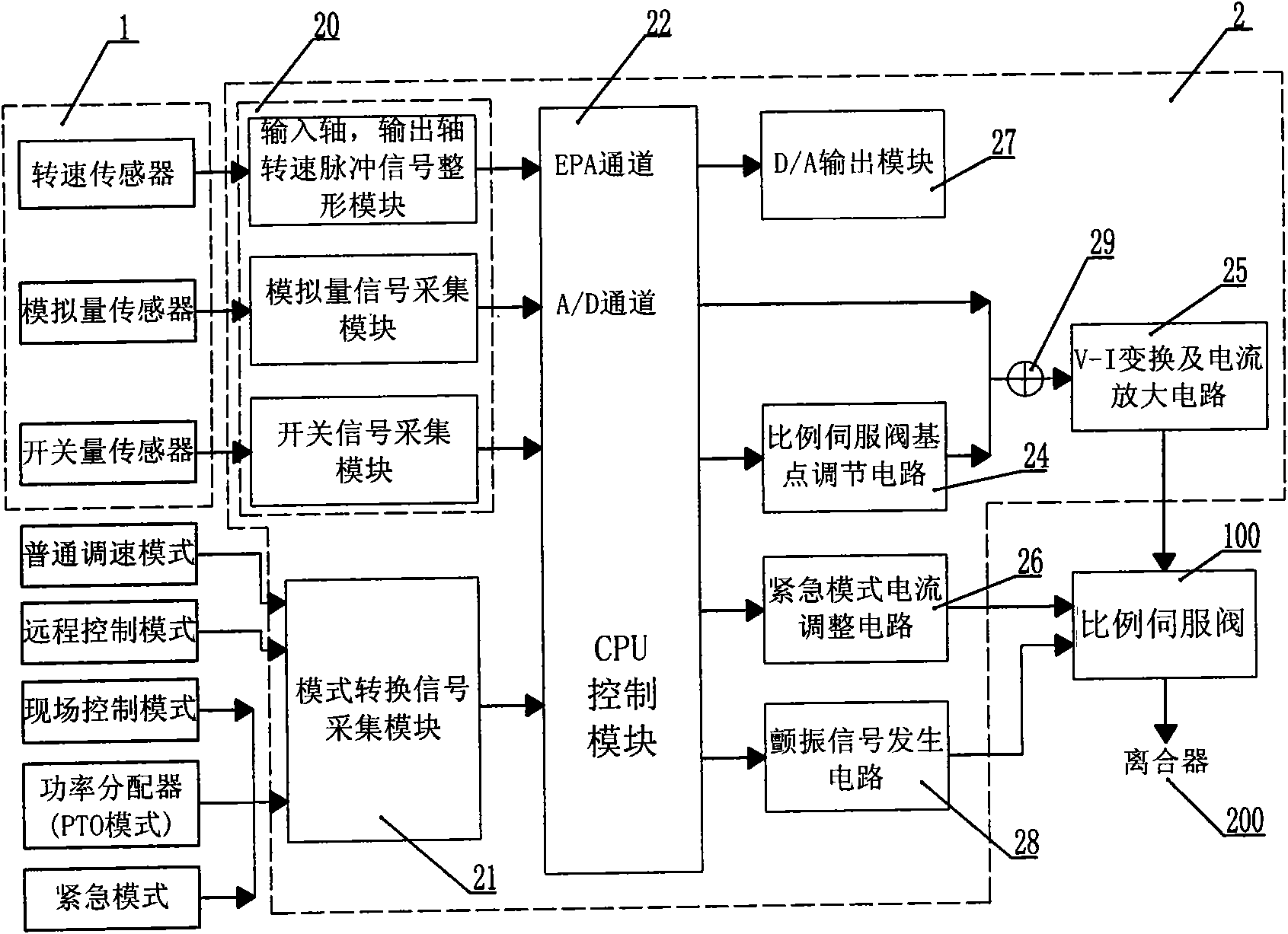
The invention relates to an applications-oriented control device of speed-regulating clutch and a control method thereof. The device comprises a sensor unit and an electronic speed-regulating controller electrically connected with the sensor unit. The electronic speed-regulating controller comprises a signal collecting module electrically connected with the output end of the sensor unit; a mode switching signal collecting module connected with a plurality of running modes; a CPU control module electrically connected with the output ends of the signal collecting module and the mode switching signal collecting module; a ratio servo valve base point regulating circuit electrically connected to the output end of the CPU control module; and a V-I converting and current amplifying circuit electrically connected with the output end accumulating the output end of the CPU control module and the output signal of the ratio servo valve base point regulating circuit. The output end of the V-I converting and current amplifying circuit drives a ratio servo valve and controls the actions of a clutch. By using a PID control policy, the invention has the advantages of adaptation to dead zone characteristics of different ratio servo valves and wide application range.

Description

technical field [0001] The invention relates to a control device and a control method of a speed regulating clutch for various applications. Background technique [0002] As a multifunctional speed regulating device, the hydraulic viscous speed regulating clutch can be used for both land use and marine use. The power machine can be an electric motor or a diesel engine, and the working state can be completely disengaged, light-load speed regulation, heavy-load speed regulation, and power distribution. And complete combination, etc., can dynamically switch between working states, if the switching process is not handled properly, it will affect the smooth operation of the fluid viscous speed clutch. [0003] The speed control of fluid viscous speed clutch has always been a research hotspot. Some domestic manufacturers have been able to produce liquid-viscous speed-regulating clutches, but most of them are manual control or relatively simple electronic control. There are many s...

Claims


Application Information

Patent Timeline
IPC IPC(8): F16D48/06
Inventor 廖鹏王天驰孙佳高晓敏张健翁建斌王秋琦吴凡
Owner SHANGHAI QIYAO HEAVY IND CO LTD
Learn More