Multi-fiber connector and method for fixing aramid fibers of fibers connected thereto

A technology of optical fiber connector and aramid fiber, which is applied in the coupling of optical waveguide and fiber mechanical structure, etc. It can solve the problem of large bending curvature and deformation range of single-core optical fiber, affecting the signal transmission effect of the connector, and large transmission loss of optical fiber signal, etc. problems, to achieve the effect of avoiding uneven glue application, avoiding glue failure problems, and increasing tensile stress points

Inactive Publication Date: 2009-10-21
CHINA AVIATION OPTICAL-ELECTRICAL TECH CO LTD
View PDF0 Cites 7 Cited by
  • Summary
  • Abstract
  • Description
  • Claims
  • Application Information

AI Technical Summary

Problems solved by technology

[0003] The optical cable leading into the connector adopts the glue potting method to peel off the end of the protective fiber (aramid fiber) attached to each optical fiber in the optical cable and then solidify it in the cured rubber block at the leading end of the optical cable in the connector housing , so that when the optical cable is pulled from the outside, the protective fibers on each optical fiber can resist the pulling of the external force, so as to realize the tensile resistance of the optical fiber, but the cured rubber block will occupy the end of the optical cable in the connector housing - the tail of the housing The larger space of the connector leads to a larger size of the tail of the connector. On the other hand, since the optical fiber protrudes from the cured rubber block to the position of the pressure plate, it does not extend along a straight line and needs to be bent to a certain extent. When the length of the housing and the position of the pressure plate remain unchanged, The thickness of the curing glue will reduce the bendable length space of the single-core optical fiber in the housing before it enters the pressure plate, resulting in a large bending curvature and deformation range of the single-core optical fiber, and the increase in the bending curvature of the optical fiber will lead to a large loss of signal transmission , affecting the signal transmission effect of the connector
[0004] In addition, each single-core optical contact is composed of an optical fiber ferrule and a ferrule part fixed at the end of the optical fiber ferrule. It is fixed in the shell by glue. The force performance of this pressure plate is poor and the problem of glue failure is difficult to solve.

Method used


Image

  • Multi-fiber connector and method for fixing aramid fibers of fibers connected thereto
  • Multi-fiber connector and method for fixing aramid fibers of fibers connected thereto
  • Multi-fiber connector and method for fixing aramid fibers of fibers connected thereto

Examples


Embodiment Construction

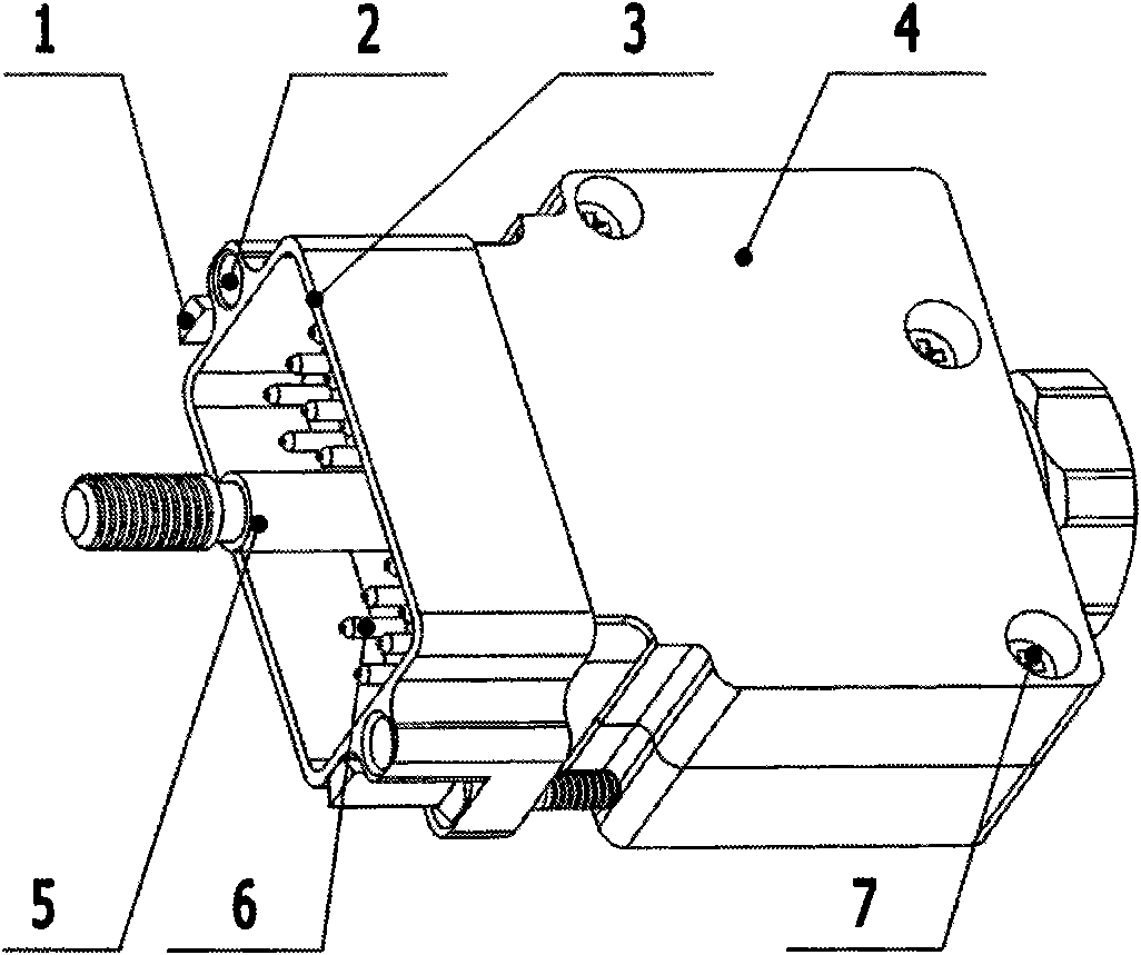
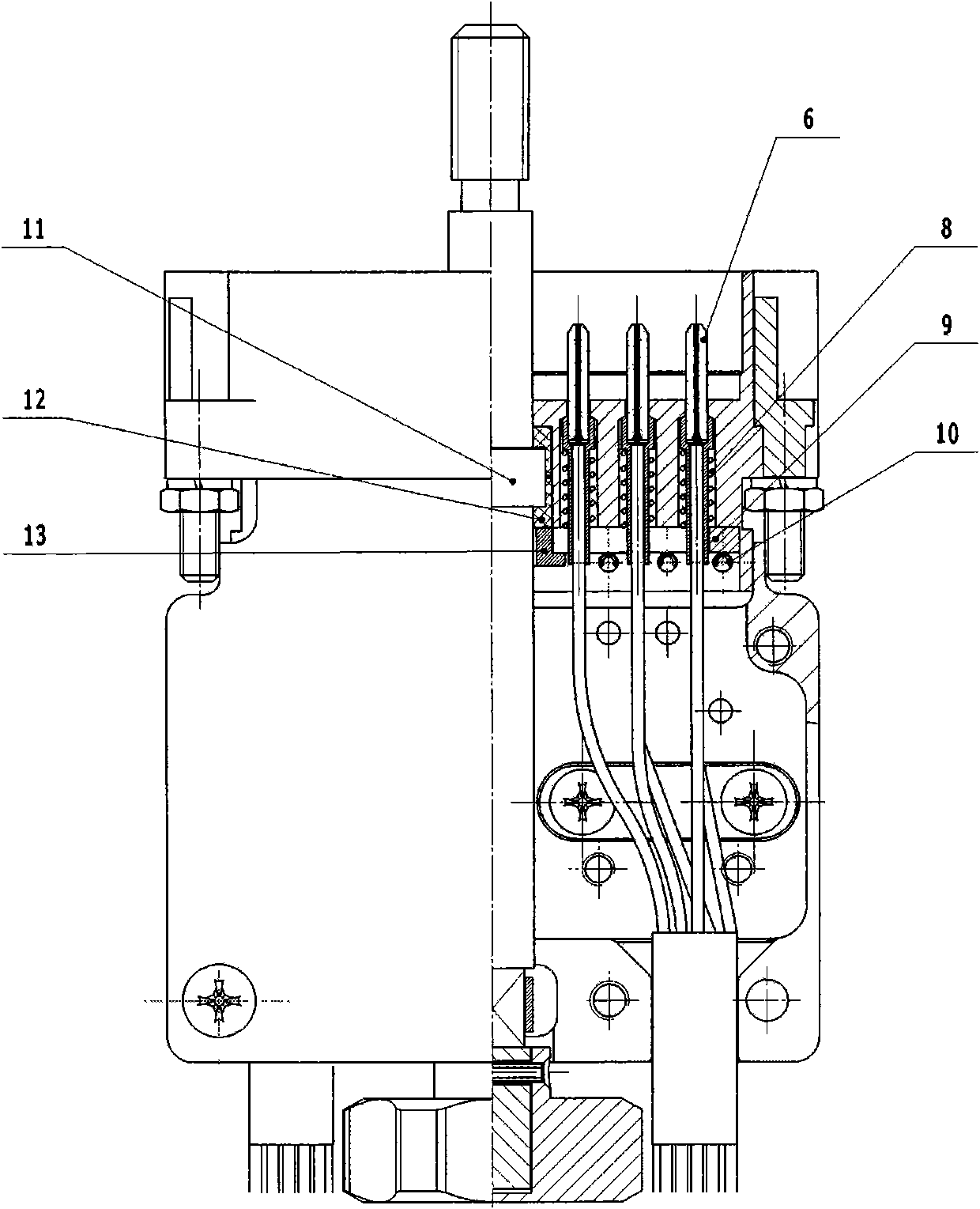
[0029] Such as Figure 1 to Figure 5 As shown, the embodiment of the multi-core optical cable connector of the present invention is a rectangular multi-core optical fiber connector plug, which includes a connector housing with a plug-in end and an optical cable access end, and the connector housing is formed by the plug-in connector of the head. The part 3 and the tail cover part 4 at the tail part are composed of a plurality of single-core contacts 6 installed in the contact installation cavity provided in the socket part 3, and each optical contact 6 includes pins and pin tails that are fixedly connected. The pin part, the contact part 3 is pressed on the end surface where the inner opening of each contact part is installed, and the contact part pressure plate 9 supporting each optical contact part 6 is pressed, and the pin part and the contact part at the end of each photo contact part 6 Springs 8 are installed on the top between the pressure plates 9, and there are two lef...


PUM


Abstract

The invention discloses a multi-fiber connector and a method for fixing the aramid fibers of the fibers connected thereto. The fixing method comprises the following steps: arranging more than one winding pinion in a shell of the fiber connector for winding the aramid fibers of the fibers; grouping the fibers connected to the fiber connector and weaving the stripped off aramid fibers of each fiber of the group of fibers into a strand; and tightly winding the strands of woven aramid fibers on near-by winding pinions. The fixing mode of the invention avoids the limitation of thickness of rubber bricks on the length of the fibers in the conventional adhesion mode, allows the fibers to run around the near-by pinions freely without being limited, and can effectively reduce the length of the shell and the curvature of the fibers and signal loss caused by the curvature, increase the tensile-resistance stress points and the mechanical performance of the aramid fibers by winding the aramid fibers on the winding pinions, simplify operation process and avoid pollution during encapsulation.

Description

technical field [0001] The invention relates to the technical field of optical fiber connectors, in particular to a multi-core optical fiber connector used for connecting a plurality of single-core optical contacts to each optical fiber of an incoming optical cable. Background technique [0002] Some existing multi-core optical fiber connectors include a housing with a plug-in end and an optical cable entry end. The housing of the connector is equipped with a plurality of single-core optical contacts, and the single-core optical contacts are plugged into the housing. The end forms a mating portion for corresponding mating with a complementary optical contact. [0003] The optical cable leading into the connector adopts the glue potting method to peel off the end of the protective fiber (aramid fiber) attached to each optical fiber in the optical cable and then solidify it in the cured rubber block at the leading end of the optical cable in the connector housing , so that wh...

Claims


Application Information

Patent Timeline
Patent Type & Authority Applications(China)
IPC IPC(8): G02B6/38G02B6/44
Inventor 姚强
Owner CHINA AVIATION OPTICAL-ELECTRICAL TECH CO LTD
Why Eureka
Try Eureka