

Vacuum pump supporting device
A technology of supporting device and vacuum pump, which is applied to the components, pump, pump element, etc. of the pumping device for elastic fluid to achieve the effect of convenient transportation and improved production efficiency
- Summary
- Abstract
- Description
- Claims
- Application Information
AI Technical Summary
Problems solved by technology
Method used
Image

Examples
Embodiment 1
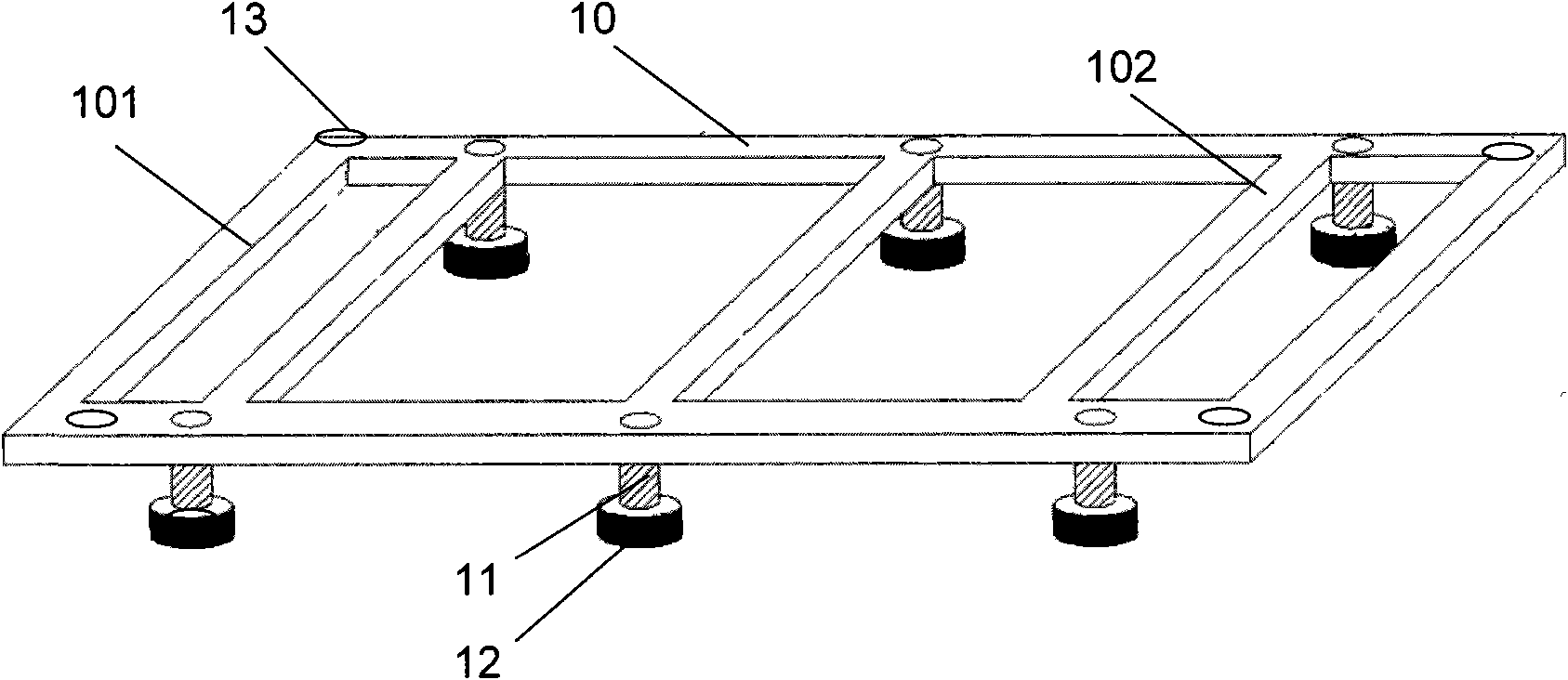
[0037] figure 2 It is a structural schematic diagram of the vacuum pump supporting device in this embodiment.
[0038] As shown in the figure, the vacuum pump supporting device includes: a bracket 10, placed under the vacuum pump (not shown in the figure); a connecting part 11, located on the lower surface of the bracket 10; shock-absorbing feet 12, composed of shock-absorbing materials , connected to the bracket 10 through the connecting portion 11 .
[0039] Wherein, support 10 has rectangular frame 101 and a plurality of support beams 102, and described support beam 102 is parallel with the short side of rectangular frame 101, is made of 5# square steel, for example, described frame long side is 1100cm, and short side is 600cm. The shape and size of the frame 101 of the bracket 10 match the shape and size of the base of the vacuum pump.
[0040] At the connecting position between the bracket beam 102 and the frame 101 , the lower surface of the bracket 10 has a connecti...
Embodiment 2
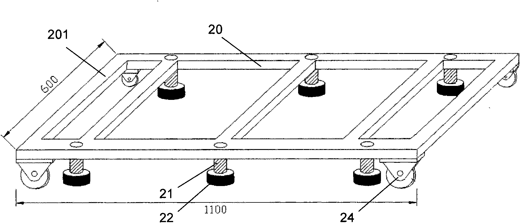
[0048] image 3 It is a structural schematic diagram of the vacuum pump supporting device in this embodiment.
[0049] As shown in the figure, the vacuum pump supporting device includes: a bracket 20, placed under the vacuum pump (not shown in the figure); a connecting part 21, located on the lower surface of the bracket 20; shock-absorbing feet 22, composed of shock-absorbing materials , is connected to the bracket 20 through the connecting portion 21, wherein the connecting portion 21 is a connecting bolt, and the shock-absorbing foot 22 is flexibly connected to the bracket 20 through the connecting bolt 21, and can be adjusted by adjusting the connecting bolt 21. The distance between the shock-absorbing feet 22 and the bracket 20 is changed.
[0050] The difference from the first embodiment is that it further includes: a support wheel 24 provided on the lower surface of the support 20 . In this embodiment, the four bracket wheels 24 are evenly distributed on the four corn...
Embodiment 3
[0056] Figure 4 It is a structural schematic diagram of the vacuum pump supporting device in this embodiment.
[0057] As shown in the figure, the vacuum pump support device includes: a bracket 30, placed under the vacuum pump (not shown in the figure); a connecting part 31, located on the lower surface of the bracket 30; shock-absorbing feet 32, composed of shock-absorbing materials , connected to the bracket 30 through the connecting portion 31, wherein the connecting portion 31 is a connecting bolt, and the shock-absorbing foot 32 is flexibly connected to the bracket 30 through the connecting bolt 31, and can be adjusted by adjusting the connecting bolt 31 The distance between the shock-absorbing feet 32 and the bracket 30 is changed.
[0058] The difference from the second embodiment is that the vacuum pump supporting device further includes: a handle seat 35 arranged on the bracket 30 and a handle 36 installed in the handle seat 35 .
[0059] In this example, if Fi...
PUM
 Abstract
Description
Claims
Application Information