Gas pressurized device

A technology of gas pressurization and pressurization cylinder, which is used in fluid pressure converters, mechanical equipment, etc., can solve the problems of poor sealing and lubrication conditions, waste of gas source, and high manufacturing cost, and achieves prevention of rigid collision, high output pressure, and high manufacturing cost. low cost effect

Active Publication Date: 2012-08-22
SICHUAN LIDI VEHICLE CHASSIS TECH CO LTD
View PDF8 Cites 1 Cited by
  • Summary
  • Abstract
  • Description
  • Claims
  • Application Information

AI Technical Summary

Problems solved by technology

This structure has the following disadvantages: 1. The concentricity requirements of the two-stage cylinder are very high, and the manufacturing cost is high
2. The sealing and lubrication conditions of the two-stage piston and cylinder are poor, and the maintenance rate is high
3. The large piston will waste half of the air source every time it reciprocates, which is a serious waste of energy
4. Using this method to pressurize the gas needs to provide the gas source and consume the gas source continuously. The whole system is complicated and the economic performance is poor.

Method used


Image

  • Gas pressurized device
  • Gas pressurized device
  • Gas pressurized device

Examples


Embodiment 1

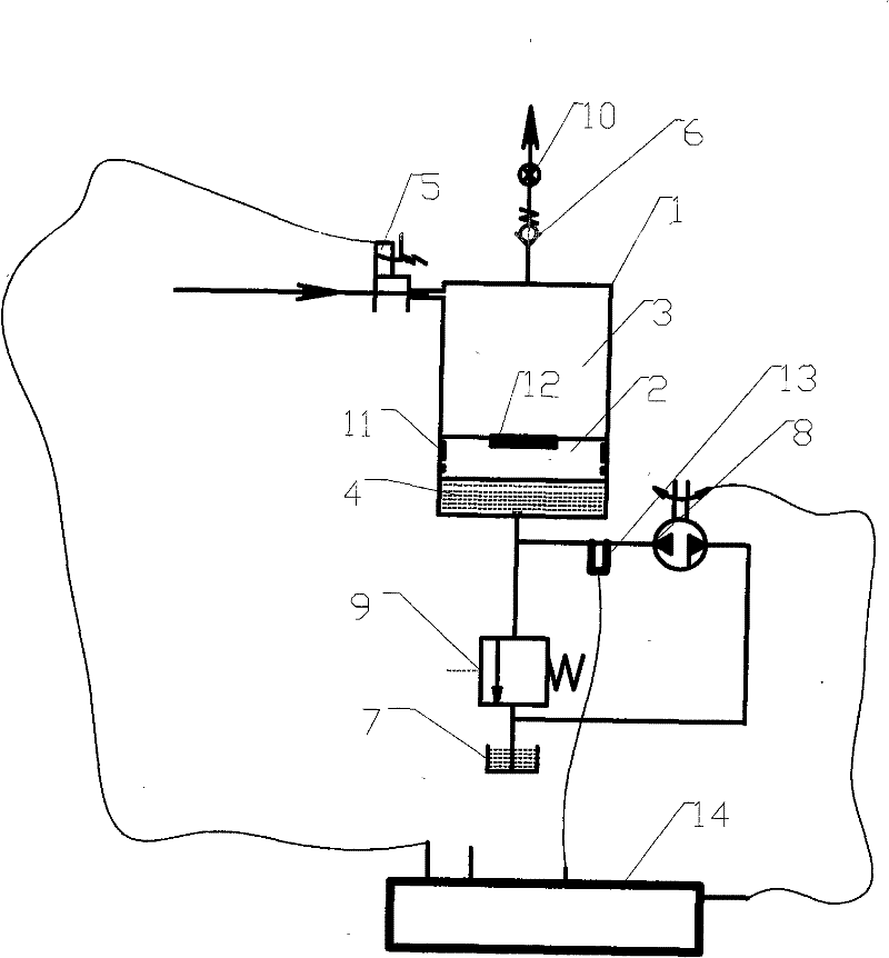
[0028] When the present invention is applied in an industrial high-pressure air supply with low requirements, it includes a booster cylinder 1, a floating piston 2 is arranged in the cylinder barrel of the booster cylinder 1, and the floating piston 2 divides the booster cylinder 1 into a booster chamber 3 and a The oil chamber 4 and the intake pipe of the pressurization chamber 3 are provided with an air intake valve 5, and the exhaust port on the upper end cover of the pressurization chamber 3 is provided with a check valve 6. The oil chamber 4 communicates with the fuel tank 7 through the oil pipe, and the oil pipe is provided with Two-way hydraulic oil pump 8 is arranged.

[0029] In the present invention, the oil pipe connecting the oil chamber 4 and the hydraulic oil pump 8 is provided with a pressure relief valve 9 installed in parallel with the hydraulic oil pump 8 . A pressure gauge 10 is installed at the outlet of the one-way valve 6 for monitoring the output pressur...

Embodiment 2

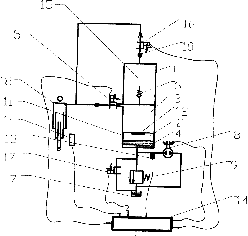
[0036] When the present invention is applied in a vehicle circulating air supply system or other circulating air systems, it includes a booster cylinder 1, a floating piston 2 is arranged in the cylinder barrel of the booster cylinder 1, and the floating piston 2 separates the booster cylinder 1 into booster cylinders. The chamber 3 and the oil chamber 4 are provided with an air intake valve 5 at the inlet of the booster chamber 3 and a check valve 6 at the outlet. The oil chamber 4 communicates with the oil tank 7 through the oil pipe, and the oil pipe is provided with a hydraulic oil pump 8 .

[0037]The present invention also includes a gas storage chamber 15, which communicates with the pressurization chamber 3 through the one-way valve 6. The gas storage chamber 15 is connected with an air delivery pipe, and an exhaust valve 16 and a pressure gauge 10 are arranged on the air delivery pipe. The air storage chamber 15 and the pressurization chamber 3 are integrated, and the...

Embodiment 3

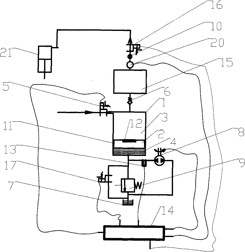
[0047] The present invention is applied to industrial high-pressure gas supply that requires stable gas supply pressure, including a booster cylinder 1, a floating piston 2 is arranged in the cylinder barrel of the booster cylinder 1, and the floating piston 2 divides the booster cylinder 1 into a booster chamber 3 And the oil chamber 4, the air intake of the booster chamber 3 is provided with an air intake valve 5, and the exhaust is provided with a check valve 6. The oil chamber 4 communicates with the oil tank 7 through the oil pipe, and the oil pipe is provided with a hydraulic oil pump 8.

[0048] The present invention also includes a gas storage chamber 15, which communicates with the pressurization chamber 3 through the one-way valve 6, the gas storage chamber 15 is connected with an air delivery pipe, and an exhaust valve 16 is arranged on the air delivery pipe. An exhaust pipe is connected between the air storage chamber 15 and the pressurization chamber 3, and the che...


PUM


Abstract

The invention discloses a gas pressurized device which comprises a pressurized cylinder. A floating piston is arranged in a cylinder barrel of the pressurized cylinder to divide the pressurized cylinder into a pressurized chamber and an oil chamber, an inlet valve is arranged at the gas inlet of the pressurized chamber, a one way valve is arranged at the gas outlet of the pressurized chamber, theoil chamber is communicated with an oil tank through an oil pipe, and a hydraulic oil pump is arranged on the oil pipe. The gas pressurized device can directly compress low pressure gas and even atmospheric pressure gas into high pressure gas, can output gas with different high pressures according to the needs, and has high output pressure as well as the advantages of high efficiency, high outputpressure, small volume, low manufacture cost, and the like.

Description

technical field [0001] The invention relates to a pressurizing device for pressurizing low-pressure gas to meet the requirements of high-pressure gas, belonging to the field of pneumatic and air control engineering, and applicable to the air supply system of vehicle air suspension and other similar systems. Background technique [0002] To pressurize the gas pressure from a lower value to 20MPA or even higher pressure, a single-stage or multi-stage gas compressor can be used. For example, Chinese Patent No. "200810008837.5" discloses a multi-stage compressor, in which a low-stage compression mechanism and a high-stage compression mechanism are provided in the casing, and the intermediate-pressure refrigerant gas compressed by the low-stage compression mechanism is sucked into the compressor. The high-stage side compression mechanism performs two-stage compression, and an injection circuit is provided to inject intermediate-pressure refrigerant extracted from the refrigerant ...

Claims


Application Information

Patent Timeline
Patent Type & Authority Patents(China)
IPC IPC(8): F15B3/00
Inventor 杨德君陈翀石正鹏
Owner SICHUAN LIDI VEHICLE CHASSIS TECH CO LTD
Why Eureka
Try Eureka