
Cable protection and guide device

A technology for guiding devices and cables, applied in the direction of chain elements, drag chains, hanging chains, etc., can solve the problems of blind holes in the link plate, high labor intensity, inability to fully ensure tensile strength and flexural rigidity, etc. Achieving the effect of reducing the burden of connection work

Active Publication Date: 2013-03-27
TSUBAKIMOTO CHAIN CO
View PDF1 Cites 0 Cited by
  • Summary
  • Abstract
  • Description
  • Claims
  • Application Information

AI Technical Summary

Problems solved by technology

[0004] However, this type of cable protection and guide device, for example, when the inner dimension of the connecting pin hole side of the preceding link frame is smaller than the outer dimension of the connecting pin hole side of the subsequent link frame, or the outer dimension of the connecting pin If the diameter is larger than the inner diameter of the connecting pin hole, it is necessary to use a large force to connect and assemble the preceding link frame and the subsequent link frame, which not only leads to greater labor intensity in the connecting and assembling operation, but also Moreover, in the case of connecting and assembling in a strong state, it may cause excessive extrusion and expansion and cause damage to the link frame.
[0005] Moreover, when this type of cable protection and guide device is miniaturized, not only the assemblability is restricted, but also the thickness of the link plate constituting the link frame cannot be increased, and the size of the connecting pin cannot be increased, so that it cannot fully Ensuring tensile strength and flexural rigidity
[0006] In addition, in this type of cable protection and guide device, in order to prevent foreign matter such as dust from intruding into the connecting pin hole, it is preferable that the connecting pin hole is formed as a blind hole closed on the plate outer surface side of the link plate. In the case of a compact size with a small inner dimension on the side of the connecting pin hole of the frame, the connecting pin hole of the link plate cannot be formed as a blind hole due to limitations in mold design

Method used


Image

  • Cable protection and guide device
  • Cable protection and guide device
  • Cable protection and guide device

Examples


Embodiment

[0034] The cable protection and guiding device according to the embodiment of the present invention will be described below with reference to the accompanying drawings.

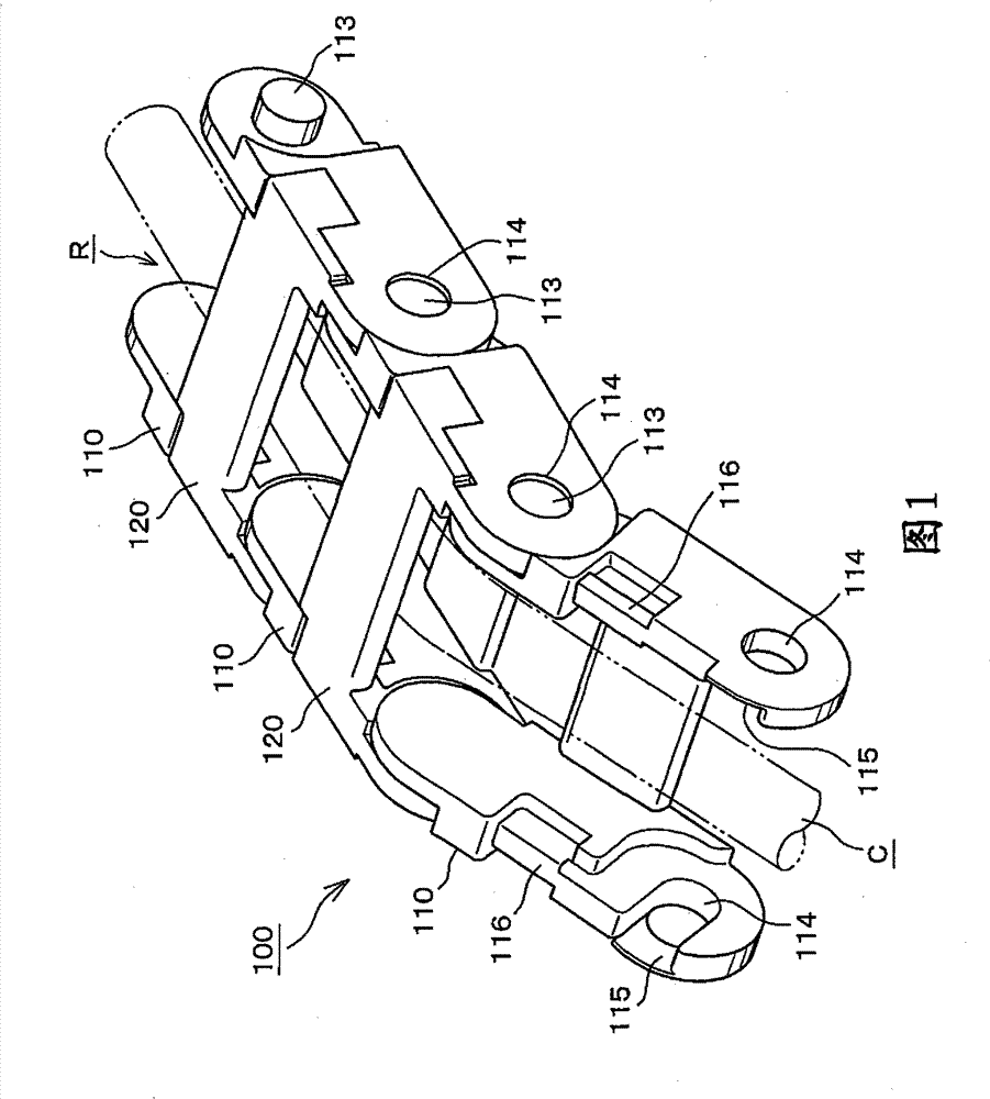
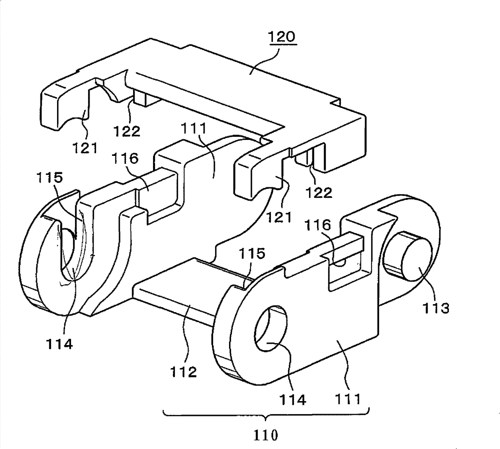
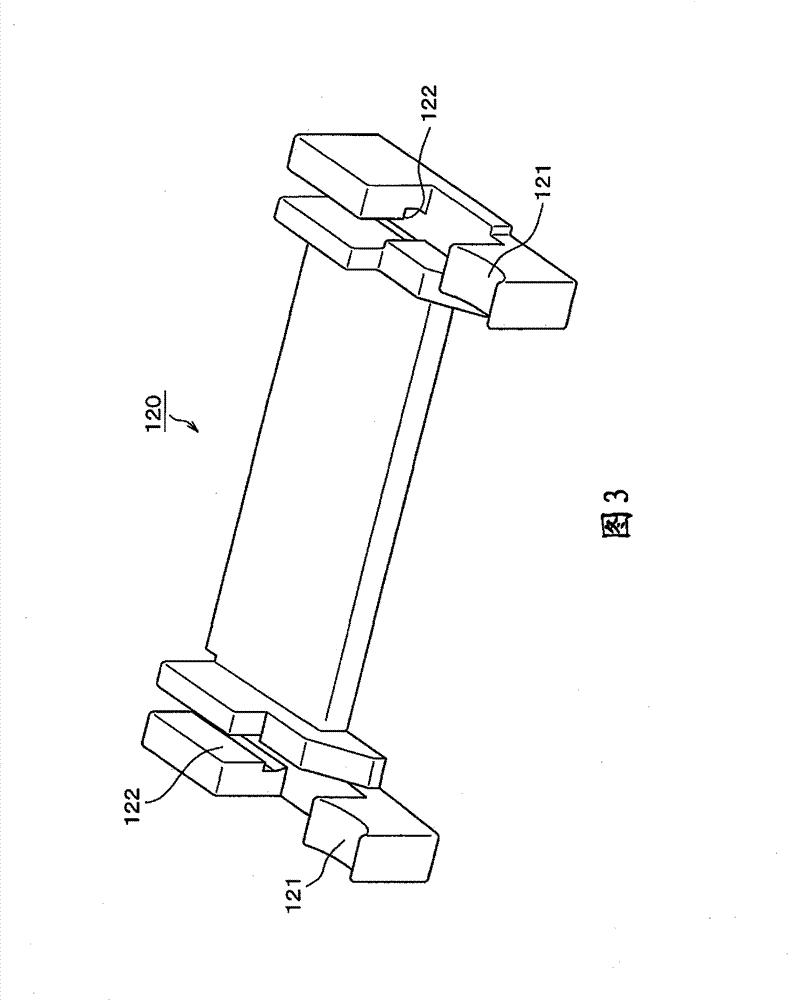
[0035] first, figure 1 It is a perspective view of the cable protection and guiding device according to the first embodiment of the present invention. figure 2 Yes figure 1 A perspective view of the link frame and cover-shaped connecting arm used in . image 3 for viewing from the back figure 2 Perspective view of the cover-like linkage arm shown. Figure 4 It is an exploded assembly view of the cable protection and guiding device according to the first embodiment of the present invention. Figure 5 It is a perspective view of the cable protection and guiding device according to the second embodiment of the present invention. Image 6 Yes Figure 5 A perspective view of the link frame and cover-shaped connecting arm used in . Figure 7 It is an exploded assembly view of the cable protection and guidi...


PUM


Abstract

A cable protection and guide device in which disengagement of a connection pin from a connecting pin hole is prevented. A cable protection and guide device in which a number of link frame bodies are flexibly and sequentially connected to each other such that a connecting pin of a preceding link plate is inserted into a connecting pin hole of the subsequent link plates. Cutout opening portions reside in the link plates. Connecting pins are inserted into the connecting pin hole 114. The connecting pins pass through a cutout portion of the side plate. Cutout opening portions in the link plates communicate with the connecting pin holes. A filling member integrally formed in the lid-shaped connecting arm seals against the connecting pin.

Description

technical field [0001] The present invention relates to cables, hydraulic hoses, pneumatic soft- Cable protection and guide devices for safe and reliable protection and guidance of flexible cables such as tubes and optical cables. Background technique [0002] The conventional protection and guiding device for cables of this type is constituted (for example, refer to Patent Document 1), and a pair of left and right link plates arranged at intervals are respectively erected laterally on the curved inner peripheral side and the curved outer peripheral side of the link plates. A rectangular chain link frame composed of a connecting plate, through which a plurality of connecting pins and connecting pin holes arranged on the chain link plate are flexibly connected to each other, and cables are inserted into the cable container formed continuously in the chain link frame Set it in the space for protection and guidance. [0003] Patent Document 1: Japanese Patent Application Laid...

Claims


Application Information

Patent Timeline
Patent Type & Authority Patents(China)
IPC IPC(8): F16G13/16
CPCF16G13/16H02G3/0475Y10S59/90H02G11/006
Inventor 小宫庄一郎开保津晃一松田孝之
Owner TSUBAKIMOTO CHAIN CO
Learn More