Lighting device, electro-optic device, and electronic device

A lighting device and light source technology, which is applied in the direction of lighting devices, fixed lighting devices, lighting and heating equipment, etc., can solve the problems of temperature rise, difficulty in realizing thinning of backlight device, and reduction of light source luminous efficiency, so as to achieve thinning, Effects of easy replacement work and easy assembly work

Inactive Publication Date: 2009-10-28
EPSON IMAGING DEVICES CORP
View PDF4 Cites 13 Cited by
  • Summary
  • Abstract
  • Description
  • Claims
  • Application Information

AI Technical Summary

Problems solved by technology

[0010] Therefore, in these backlight devices, the thickness of the light source unit becomes large, so a space capable of accommodating the light source unit has to be provided, and there is a problem that it is difficult to reduce the thickness of the backlight device.
[0011] In addition, vertical backlights generally have a structure in which a light source unit is arranged in a casing made of resin or metal. When the luminance of the light source is to be increased, the temperature inside the casing rises due to the heat generated from the light source. As a result, the luminous efficiency of the light source decreases.

Method used


Image

  • Lighting device, electro-optic device, and electronic device
  • Lighting device, electro-optic device, and electronic device
  • Lighting device, electro-optic device, and electronic device

Examples


no. 1 Embodiment approach

[0054] (Structure of liquid crystal device)

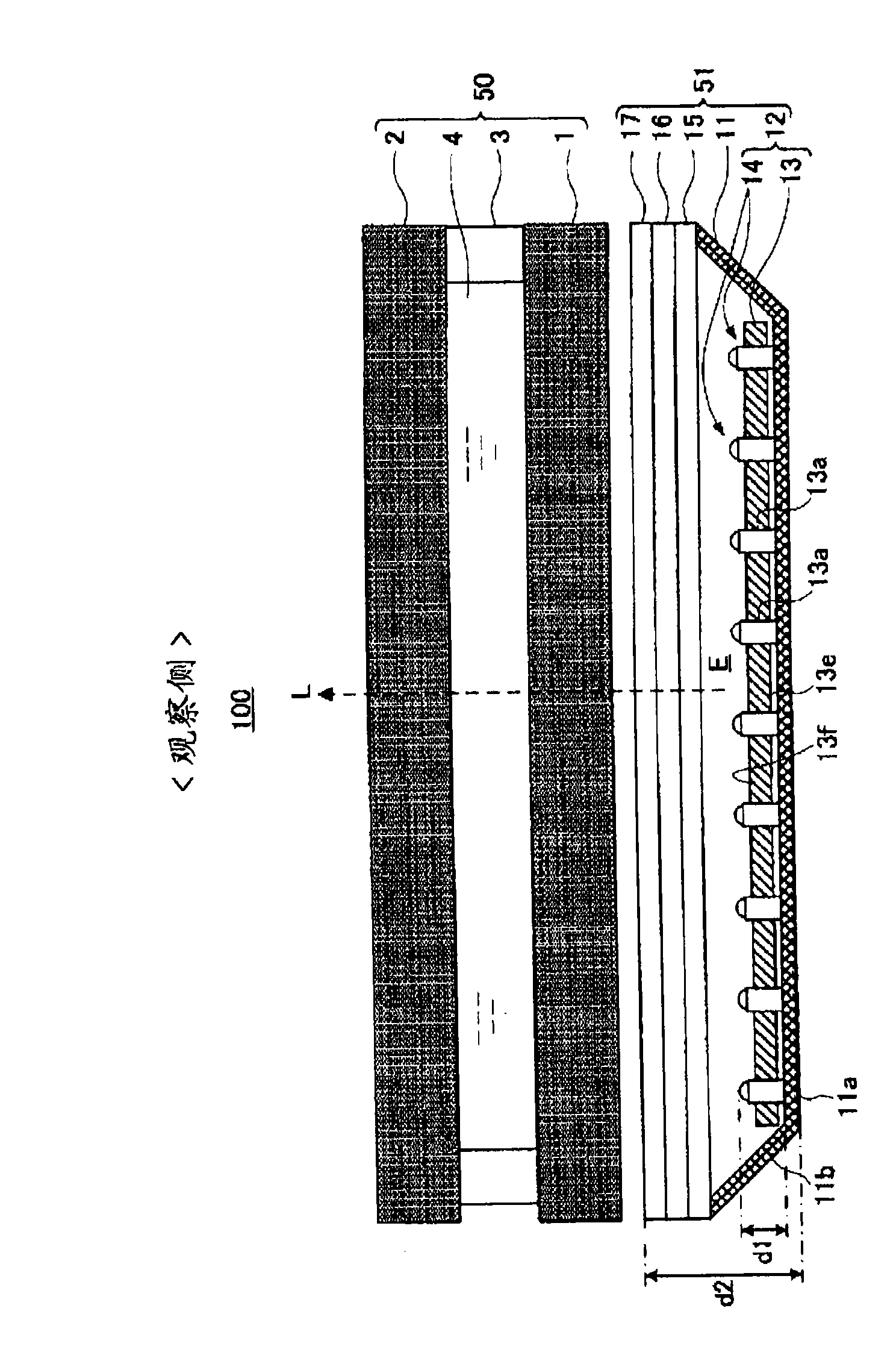
[0055] First, refer to Figure 1 to Figure 3 Next, the structure of the liquid crystal device 100 as an example of the electro-optical device according to the first embodiment of the present invention will be described.

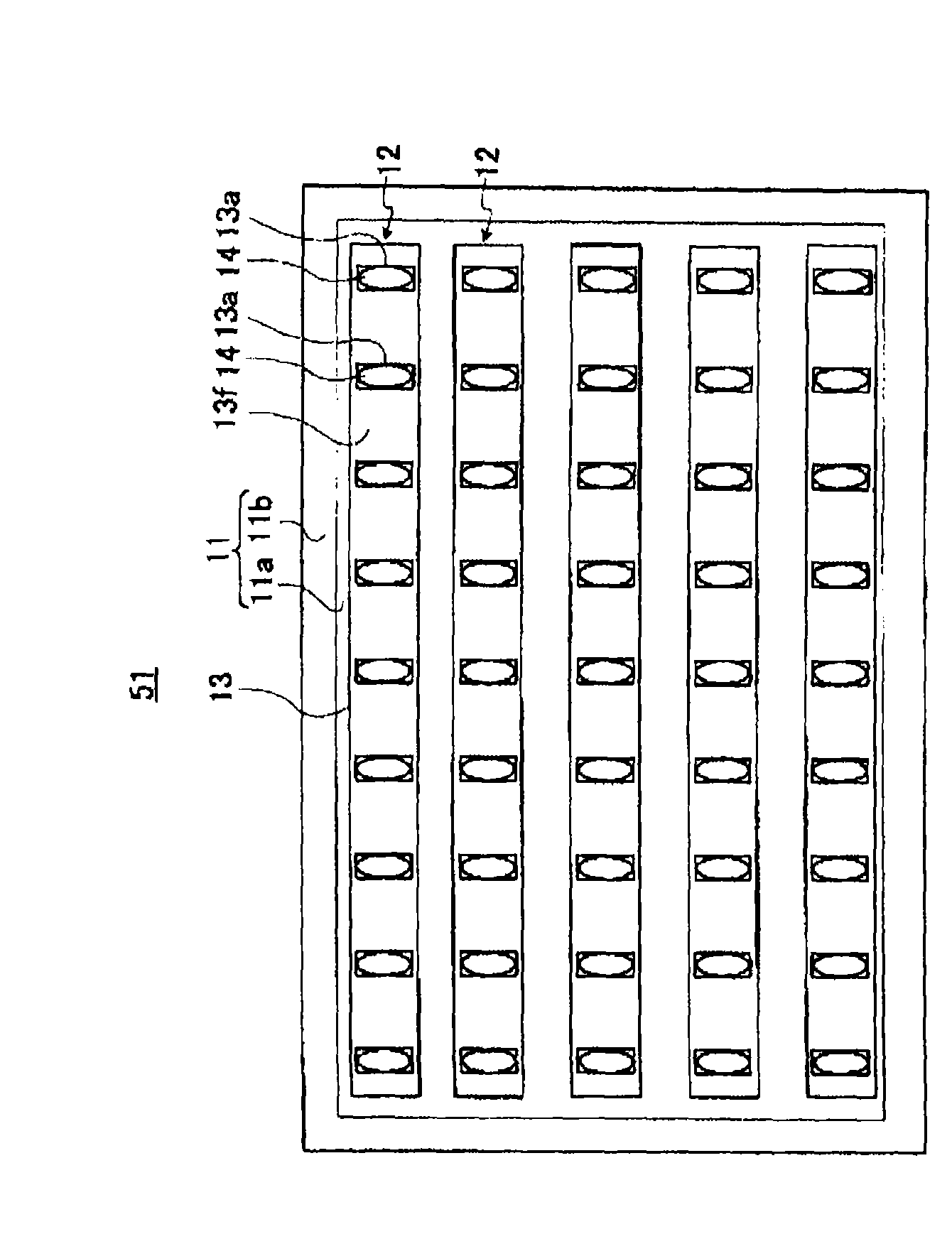
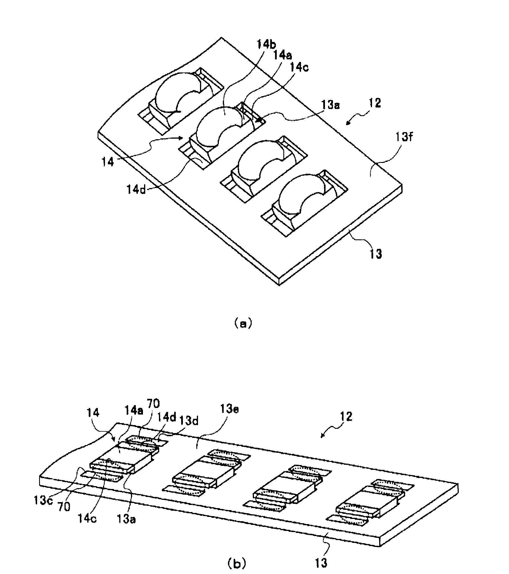
[0056] figure 1 It is a cross-sectional view showing a schematic configuration of the liquid crystal device 100 in the first embodiment. figure 2 means from figure 1 A plan view of the illuminating device 51 as a constituent element of the liquid crystal device 100 seen from the observation side (the side recognized by the observer) of . But when figure 2 In the figure, illustration of various optical sheets that are elements of the lighting device 51 is omitted for convenience. image 3 (a) is a perspective view showing main parts of the light source unit 12 seen from the light emitting side of the light source 14 . image 3 (b) shows a perspective view of main parts of the light source unit 12 seen from ...

no. 2 Embodiment approach

[0073] Below, refer to Figure 4 (a) and (b) demonstrate the structure of the liquid crystal device 100a provided with the illumination device 51a in 2nd Embodiment of this invention.

[0074] Figure 4 (a) is a sectional view which shows the schematic structure of the liquid crystal device 100a provided with the illumination device 51a of 2nd Embodiment. Figure 4 (b) is with image 3 (b) Correspondingly, a perspective view of main parts of the lighting device 51a showing the arrangement relationship between the heat dissipation member 18 and the light source unit 12 in the second embodiment.

[0075] When comparing the second embodiment with the first embodiment, in the second embodiment, a heat dissipation member for dissipating the heat generated by the light source 14 is provided in the lighting device 51a. are different, but otherwise the structure is the same. Therefore, hereinafter, the same reference numerals are assigned to the same elements as those in the first...

no. 3 Embodiment approach

[0081] Below, refer to Figure 5 and Figure 6 The structure of the liquid crystal device provided with the illumination device 51b in 3rd Embodiment of this invention is demonstrated.

[0082] Figure 5 It shows the top view of the illuminating device 51b in 3rd Embodiment seen from the observation side. But when Figure 5 In the figure, illustration of various optical sheets that are elements of the lighting device 51b is omitted for convenience.

[0083] Figure 6 (a) is a perspective view showing main parts of the circuit board 13x constituting the light source unit 12x in the third embodiment. Figure 6 (b) shows a perspective view of main parts of the light source unit 12x seen from the light emission side of the light source 14. FIG. Figure 6 (c) shows a plan view of main parts of the light source unit 12x seen from the side opposite to the light emitting side of the light source 14 .

[0084] When comparing the liquid crystal device in the third embodiment with...


PUM


Abstract

The invention relates to a lighting device, a liquid crystal display device and an electronic device; miniaturization and thin type of a light source unit can be realized in a vertical typed lighting device. The lighting device is a so-called vertical type lighting device, and comprises a circuit board and light source units of a plurality of light sources connected with the circuit board. Particularly in the light source unit, each light source is allocated on the circuit board in a manner that at least part of the light source is positioned on the width direction of the circuit board or the internal part of the circuit board. Concretely, each light source is allocated on the circuit board in a state that at least a part of base material composing each light source enters run-through holes arranged on the circuit board. Therefore, at least a part of each light source is partially overlapped with the width direction part of the circuit board or the internal part of the circuit board. Thus, the width of the light source unit can become thinner compared with the light source unit formed by allocating light source on the circuit board.

Description

technical field [0001] The present invention relates to the structure of a lighting device suitable for electro-optical devices and the like. Background technique [0002] Currently, in electronic devices such as mobile phones, portable information terminals, and computer monitors, liquid crystal devices, which are examples of electro-optical devices, are widely used for displaying images. [0003] In such a liquid crystal device, a backlight device (illumination device) is provided on the back side of the liquid crystal display panel in order to illuminate the liquid crystal display panel from the back side to perform transmissive display. The lighting device is mainly classified into two types, a vertical type (direct type) and an edge light type, according to the arrangement position of the light source relative to the liquid crystal display panel or the like. [0004] A vertical lighting device is a lighting device in which a light source is arranged on the back side of...

Claims


Application Information

Patent Timeline
Patent Type & Authority Applications(China)
IPC IPC(8): F21S8/00F21V19/00G02F1/13357F21Y101/02G02F1/1335
Inventor 美田淳也百濑佳典丸山明美滨晋太郎
Owner EPSON IMAGING DEVICES CORP
Why Eureka
Try Eureka