
Wall charger

A charger and wall technology, applied in the field of chargers for digital devices, can solve the problems of recycling problems, environmental protection, single use of chargers, increase in the number of chargers, etc., and achieve the effect of improving the use value.

Inactive Publication Date: 2009-10-28
深圳知己迅联通讯有限公司
View PDF0 Cites 4 Cited by
  • Summary
  • Abstract
  • Description
  • Claims
  • Application Information

AI Technical Summary

Problems solved by technology

[0002] At present, due to the large-scale popularization of mobile phones and portable digital devices such as MP3 and MP4, especially the diversification and complexity of the distribution of people using mobile phones, usage patterns and places of use, it is difficult to standardize the charging sockets of mobile phones, resulting in the charging of mobile phones. single use only
Although the configuration of mobile phone chargers has been initially unified after the implementation of the YD / T-1591 standard in our country, it has been changed to connect and charge with a handheld charger with a USB socket through a USB data cable, but as the number of mobile phones is increasing, all The corresponding number of configured handheld chargers has also increased, and even the number of chargers used is more than the number of mobile phones due to differences in voltage and AC sockets in different countries.
The disadvantages of the above-mentioned status quo are: first, the single use of chargers leads to an increase in the number of chargers and a serious waste of resources (plastic, metal, electronic components), and there are recycling problems and environmental protection problems; Second, the single use of the charger and the non-uniform charging interface standards lead people to carry the handheld charger with them in daily life, causing burden and inconvenience to travel, and it is still limited by the perfection of regional power supply facilities when charging is urgently needed

Method used


Image

  • Wall charger
  • Wall charger
  • Wall charger

Examples


Embodiment Construction

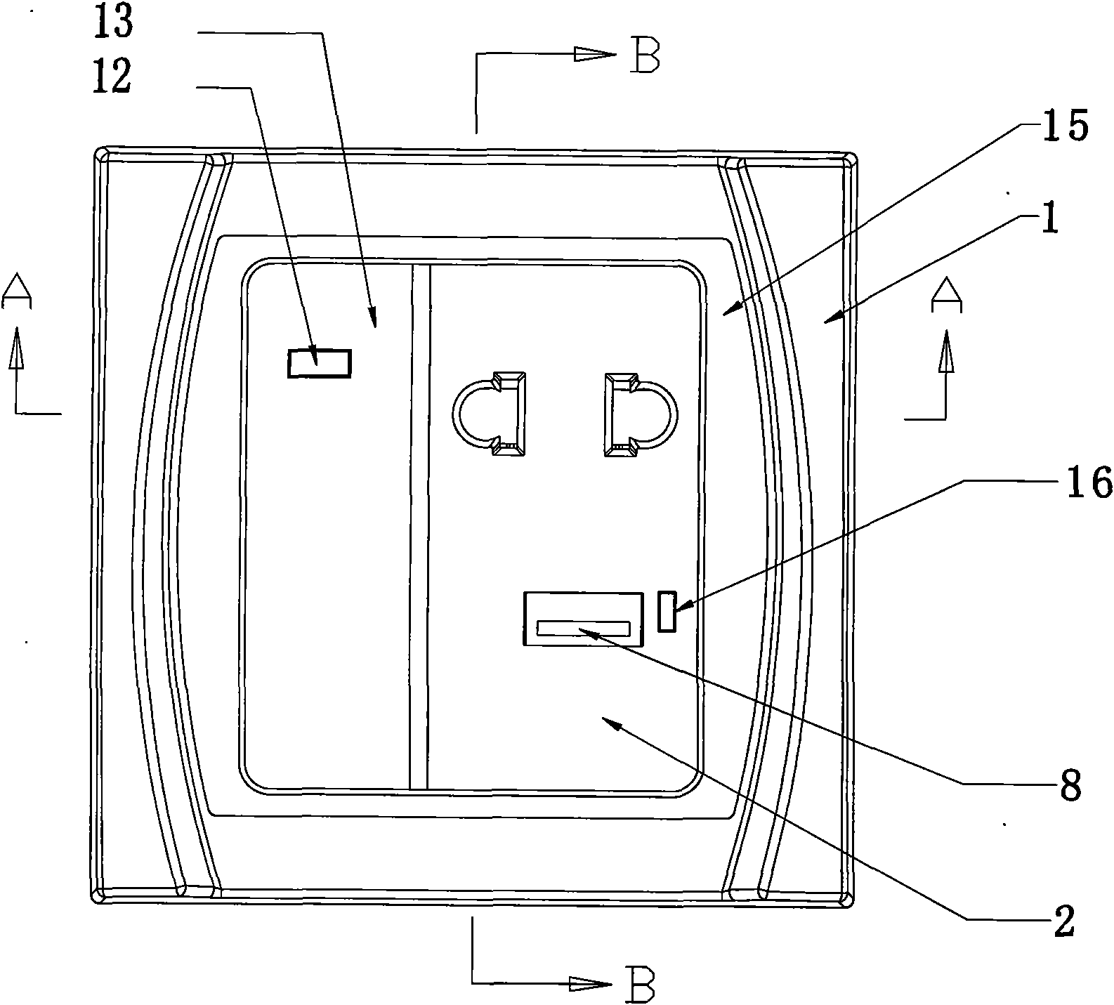
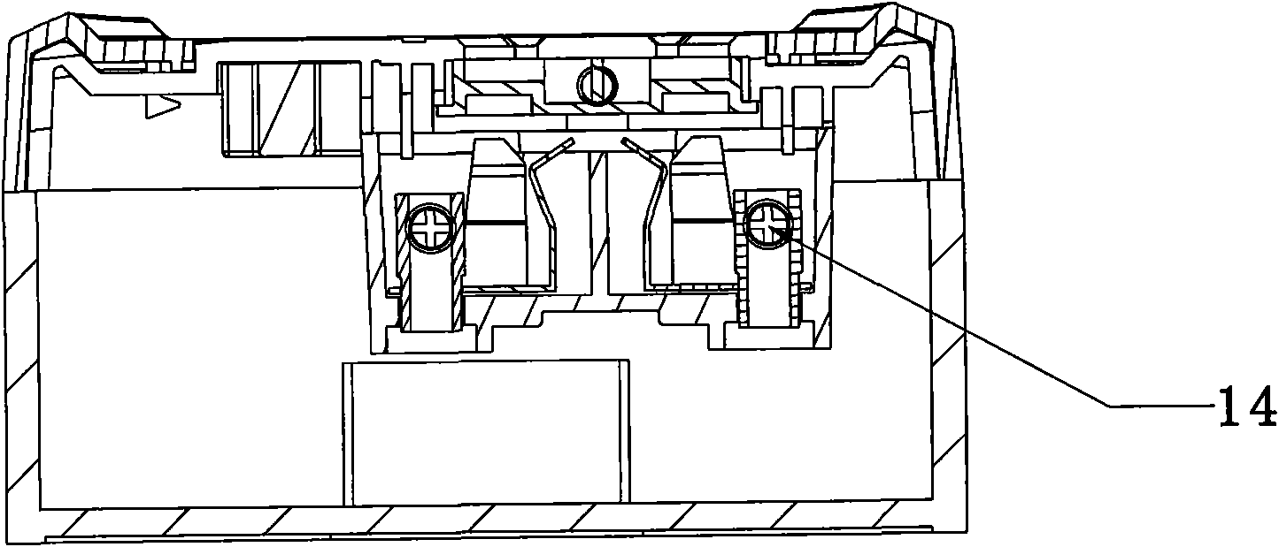
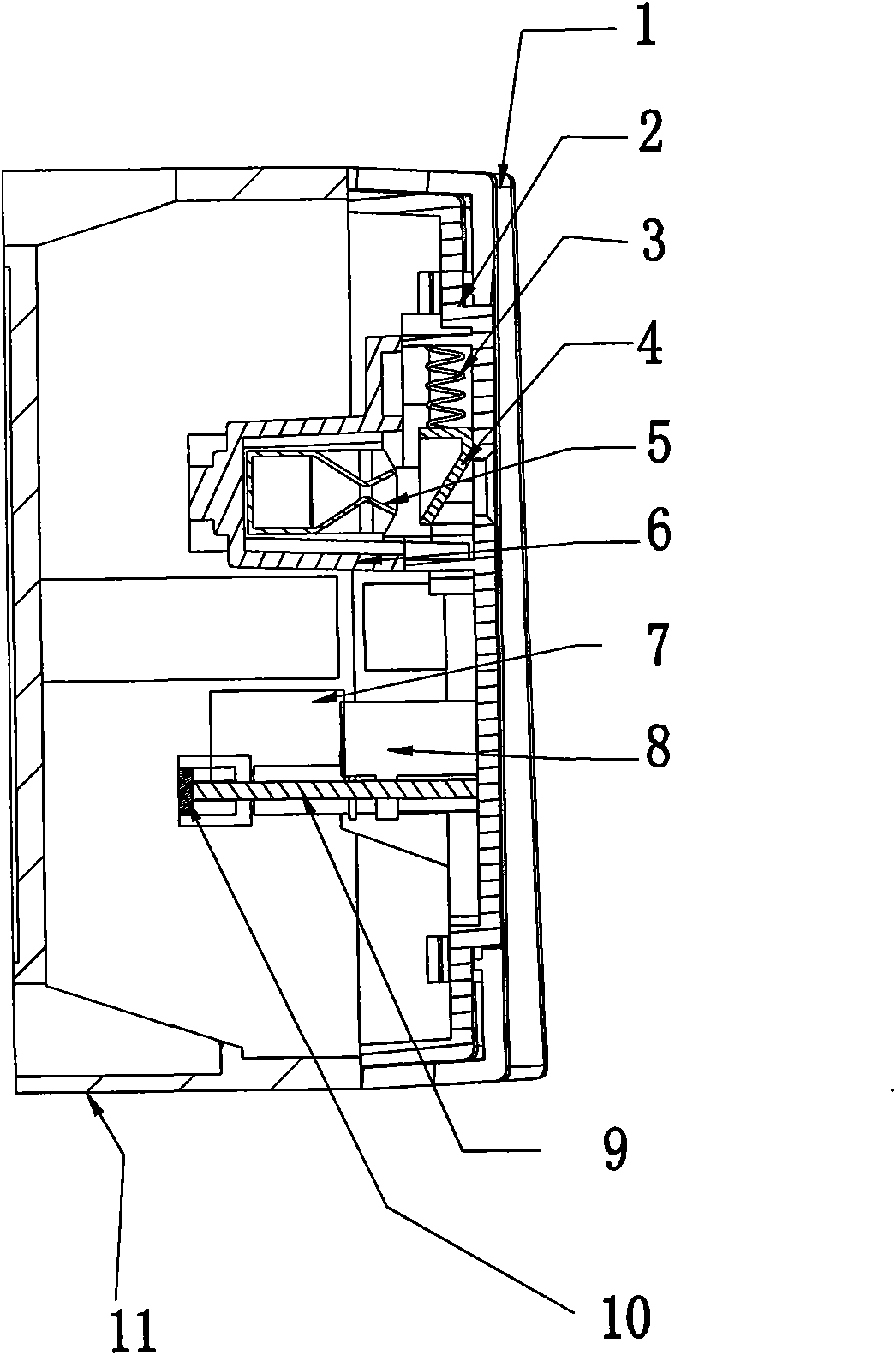
[0019] The present invention will be further described below in conjunction with the accompanying drawings. Such as figure 1 , figure 2 , image 3 and Figure 4 As shown, the wall charger of the present invention is composed of a housing, a USB output charging mechanism and an AC socket located in the housing, and the USB output charging mechanism is a PCBA (Printed Circuit Assembly Board, Printed Circuit Assembly Board) with a USB output charging function. Board Assembly) 9, the PCBA9 is composed of a transformer 7, a USB socket 8, a rectifier circuit, a high-frequency switch circuit, and an overvoltage and overcurrent protection integrated circuit. and USB socket 8, the high-frequency switch circuit controls circuit on-off work in a high-frequency manner to save energy. The AC socket is composed of a socket shrapnel 5 and a fixing piece 6 fixed on the front cover. The housing is composed of a face cover 1 and a rear cover 11 , the face cover 1 is provided with a front ...


PUM


Abstract

The invention discloses a wall charger which solves the problem that the charger can meet the requirement of providing alternative current socket function for inside and outside of a room and public facilities under the condition of meeting the demand of charging by a USB data wire. The wall charger comprises a casing as well as a USB output charging mechanism and an alternative current socket which are arranged in the casing, wherein the USB output charging mechanism is a printed circuit assembly board with USB output charge function, which is provided with a transformer, a rectification circuit, an inductance and a USB socket; the printed circuit assembly board is provided with a high-frequency switch circuit and an integration circuit with overvoltage and overcurrent protection function; and the alternative current socket consists of a socket elastic piece and a fixed piece fixed at a front cover. The invention is additionally provided with a PCBA socket and a USB socket on a common wall socket for charge, which can charge a cellphone and can be used as a wall power supply socket of an electric appliance, thereby improving the use value of a single product.

Description

technical field [0001] The invention relates to a charger, in particular to a charger for a digital device fixed on a wall. Background technique [0002] At present, due to the large-scale popularization of mobile phones and portable digital devices such as MP3 and MP4, especially the diversification and complexity of the distribution of people using mobile phones, usage patterns and places of use, it is difficult to standardize the charging sockets of mobile phones, resulting in the charging of mobile phones. For single use only. Although the configuration of mobile phone chargers has been initially unified after the implementation of the YD / T-1591 standard in our country, it has been changed to connect and charge with a handheld charger with a USB socket through a USB data cable, but as the number of mobile phones is increasing, all The number of configured handheld chargers has also increased, and even the number of chargers used is greater than the number of mobile phon...

Claims


Application Information

Patent Timeline
IPC IPC(8): H01M10/44H02J7/00
CPCY02E60/12Y02E60/10
Inventor 李庭光李泽秉
Owner 深圳知己迅联通讯有限公司
Learn More