
Microwave frequency measuring method based on optical power detection and device thereof

A microwave frequency measurement and optical power detection technology, applied in electromagnetic wave transmission systems, transmission monitoring, electrical components, etc., can solve the problems of limited bandwidth of the linear frequency demodulation frequency band, high system complexity and high cost, to eliminate the impact and expand the measurement. frequency bands, the effect of reducing complexity and cost

Inactive Publication Date: 2009-10-28
SOUTHWEST JIAOTONG UNIV
View PDF1 Cites 36 Cited by
  • Summary
  • Abstract
  • Description
  • Claims
  • Application Information

AI Technical Summary

Problems solved by technology

Although this scheme only needs a low-speed optical detector or optical power meter, this measurement scheme requires two continuous light sources, and the complexity and cost of the system are still high. In addition, the fluctuation of the output power of the two continuous light sources will affect the frequency measurement. Negative impact; the correspondence between the optical power ratio and the microwave frequency is a tangent function shape, and the broadband with linear frequency demodulation band is limited

Method used


Image

  • Microwave frequency measuring method based on optical power detection and device thereof
  • Microwave frequency measuring method based on optical power detection and device thereof
  • Microwave frequency measuring method based on optical power detection and device thereof

Examples


Embodiment Construction

[0021] The present invention will be further described below in conjunction with the accompanying drawings.

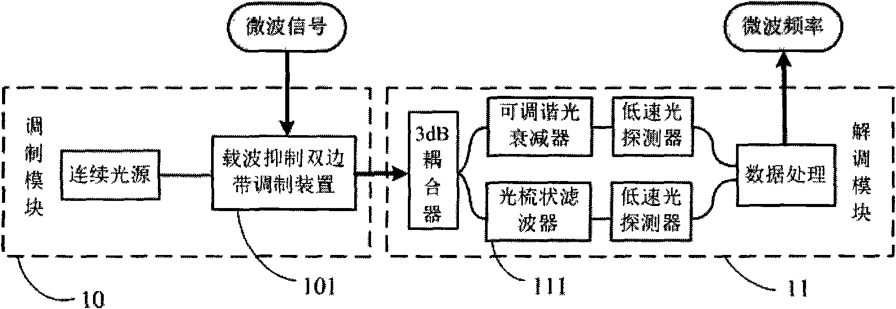
[0022] Such as figure 1 As shown, the measurement system includes an electro-optical modulation module 10 of carrier suppression type small signal modulation and a demodulation module 11 with an arcsine function-shaped frequency demodulation curve. In the electro-optic modulation module, the microwave signal received from the outside is loaded onto a continuous light source in the form of small signal modulation through the electro-optic modulator; the carrier suppression condition is introduced, and the modulated optical signal only generates two optical edges of ±1 order bring.

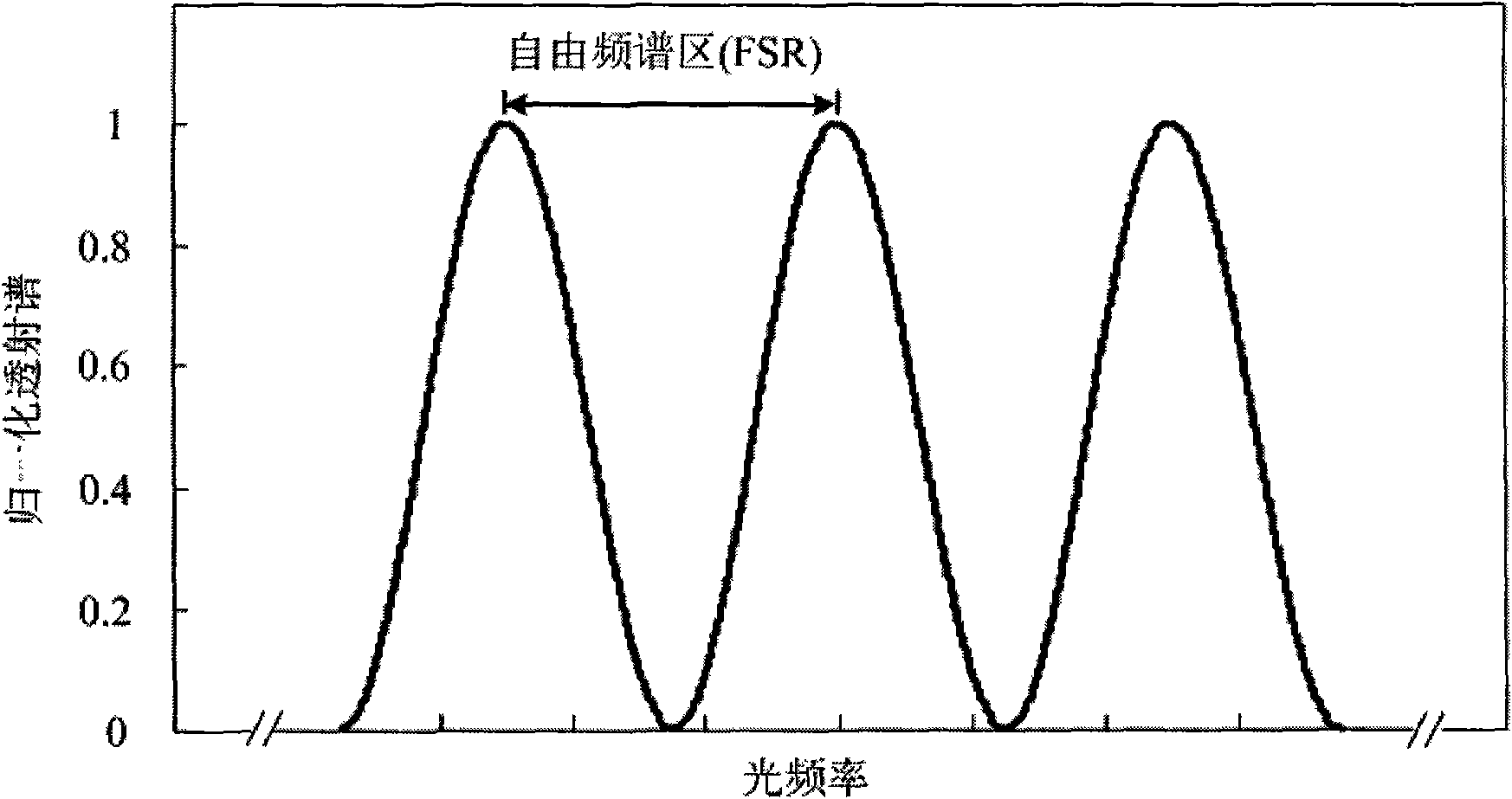
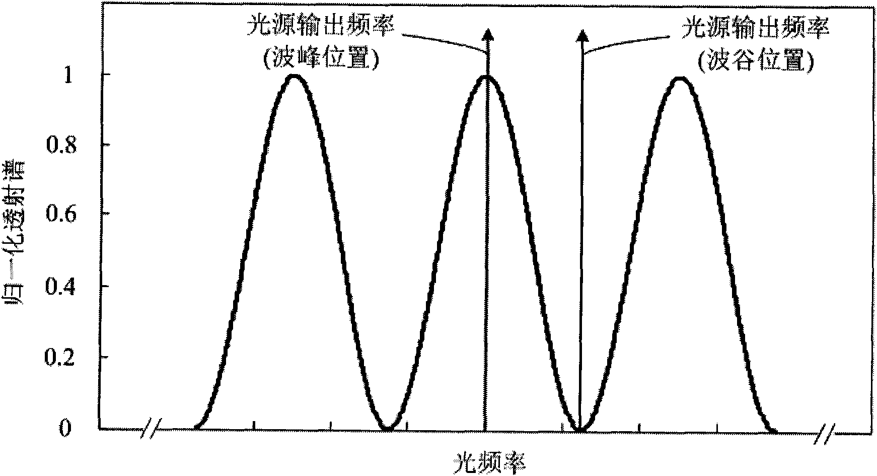
[0023] The output optical signal of the modulation module is injected into the demodulation module. In the demodulation module, the optical signal composed of ±1-order optical sidebands is divided into two paths: one path is injected into a comb filter with sinusoidal function type transmi...


PUM


Abstract

The invention discloses a microwave frequency measuring method based on optical power detection and a device thereof, which conducts real-time measurement on microwave frequency by adopting a system consisting of an electro-optical modulating module and a frequency demodulating module. A continuous microwave signal is loaded on a continuous light source in the modulating module in the modulating manner of carrier suppressed small signals, and only generates two plus or minus 1 stage optical margin strips; the modulated optical signal is divided into two paths, wherein one path is injected into a comb-like filter with sine-function transmission spectrum while the other path is injected into a tunable optical attenuator; the output optical power of the two paths are detected and compared with each other and the microwave frequency is obtained from the demodulation of power ratio. The invention lowers the complexity and cost of the system, eliminates the influence of fluctuation of output power of the light source on the measurement of the frequency and enlarges the measuring frequency band of frequency linear demodulation.

Description

technical field [0001] The invention relates to the field of communication and signal processing, in particular to a photon technology type real-time microwave frequency measurement method. Background technique [0002] Real-time microwave frequency measurement is an important content in the field of military and civilian microwave communication and signal processing, involving frequency tracking, communication monitoring, etc. Most of the early microwave frequency measurement techniques were based on electronic techniques, such as electric spectrum analyzers. Electron spectrum analyzers work in a scanning mode. When the existence time of the microwave signal to be measured is less than one scan period, the spectrum analyzer cannot normally obtain its frequency information. However, in some important fields (such as electronic warfare), the communication or signal is very sudden and exists for a short time, and the scanning mode frequency measurement method is difficult to...

Claims


Application Information

Patent Timeline
IPC IPC(8): H04B10/08H04B17/00H04B10/075
Inventor 邹喜华潘炜罗斌闫连山张志勇
Owner SOUTHWEST JIAOTONG UNIV
Learn More