Electric tool brake apparatus

A braking device and electric tool technology, applied in the direction of mechanically driven drum brakes, sawing machine devices, manufacturing tools, etc., can solve problems such as high cost and complex structure

Inactive Publication Date: 2009-11-04
POSITEC POWER TOOLS (SUZHOU) CO LTD
View PDF1 Cites 5 Cited by
  • Summary
  • Abstract
  • Description
  • Claims
  • Application Information

AI Technical Summary

Problems solved by technology

This structure is more complex, there are more hinges, and a switch and

Method used


Image

  • Electric tool brake apparatus
  • Electric tool brake apparatus
  • Electric tool brake apparatus

Examples


Embodiment Construction

[0035] The disclosure of the present invention discloses a braking device for an electric tool, in particular a braking device for a chainsaw, and the present invention will now be described in specific embodiments.

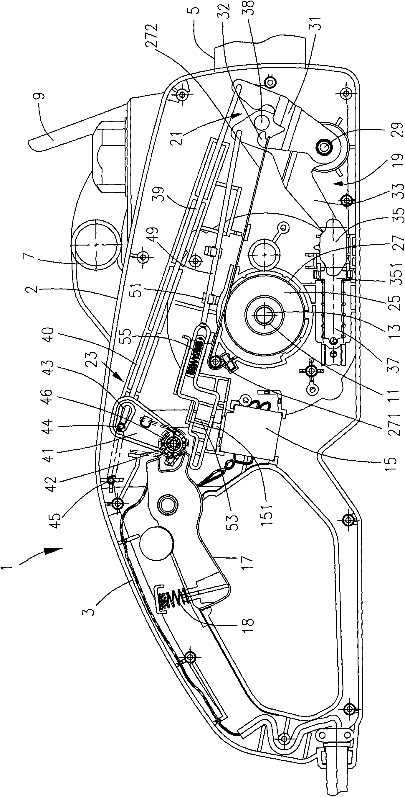
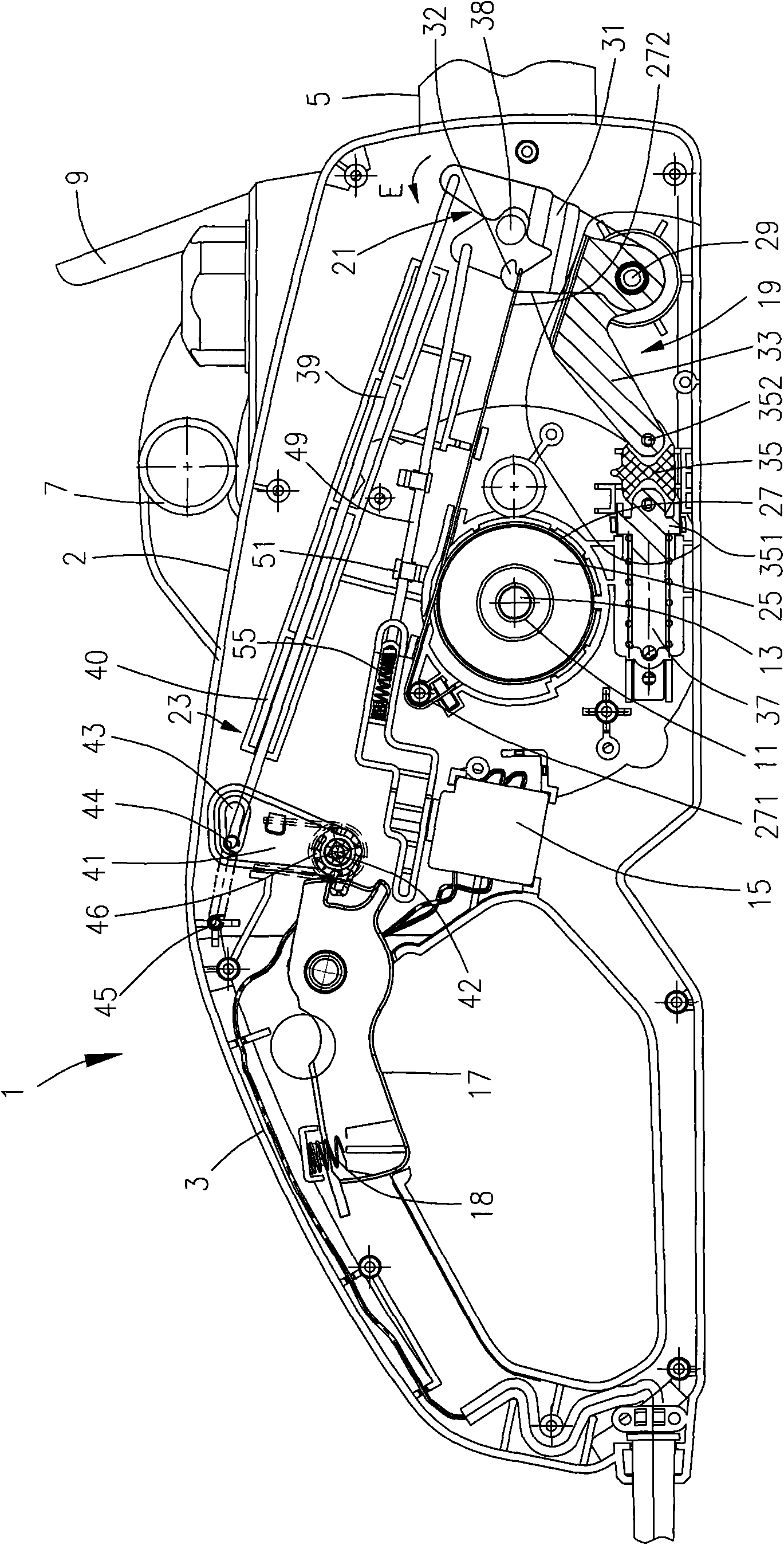
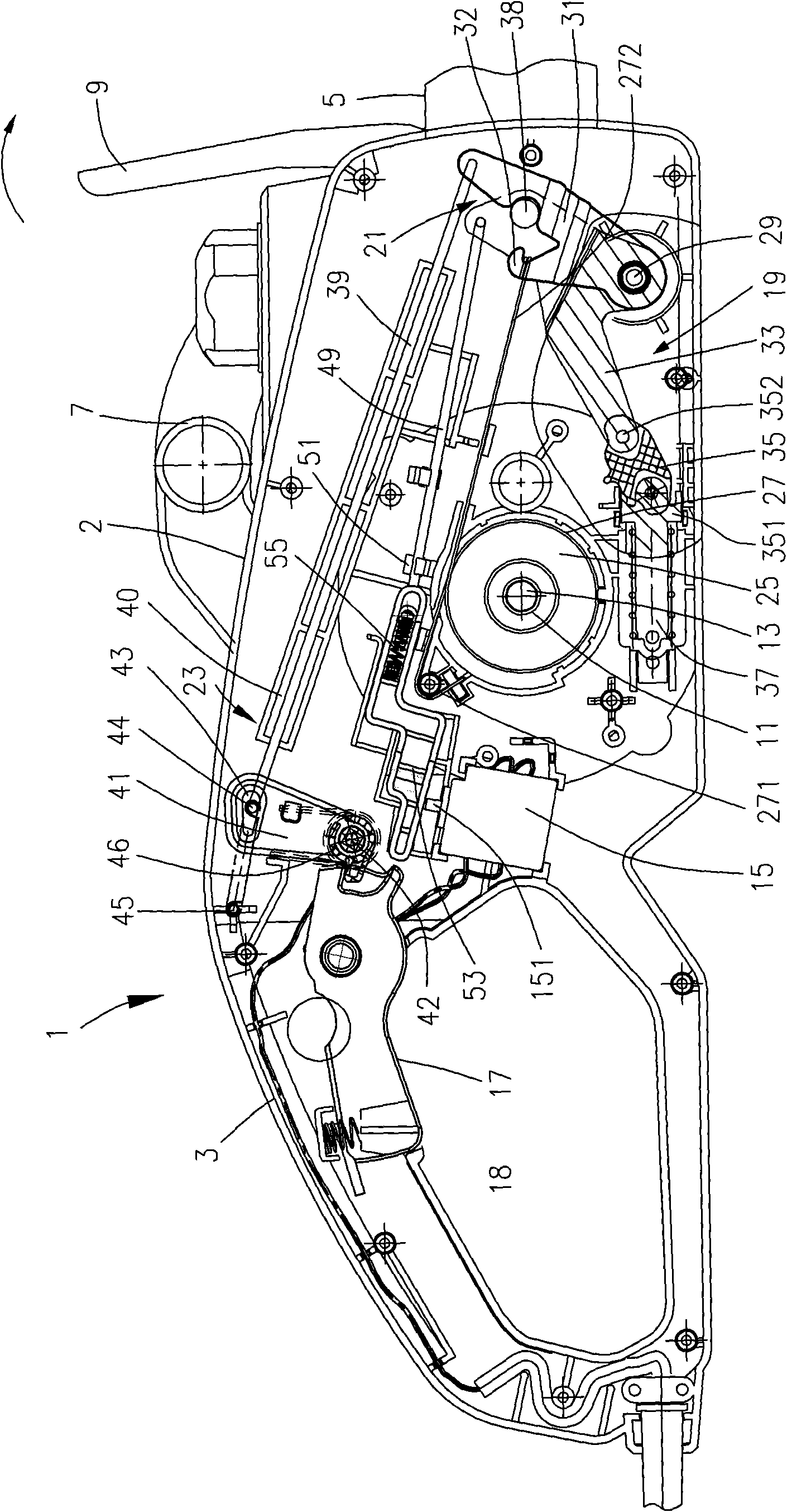
[0036] refer to figure 1 As shown, in the preferred embodiment of the present invention, the chain saw 1 has a housing 2 extending longitudinally, a first handle 3 is provided at the rear end of the housing, and a front end of the housing 2 can be lined with a In the chain plate 5 of the guide saw chain (not shown in the figure), a second handle 7 is also provided near the front end of the housing 2, and the second handle 7 is located above the housing 2 and perpendicular to the housing 2. in the longitudinal direction of the Figure 1 to Figure 3extends perpendicular to the plane of the drawing. The driving device 11 of a chainsaw is provided in the housing 2, and the driving device includes the motor of the chainsaw, the output shaft 13 of the chainsaw motor ...


PUM


Abstract

The invention discloses an electric tool brake apparatus comprising a work piece and a brake apparatus used for fast stopping the movement of the work piece, wherein the brake apparatus comprises a brake drum, a brake ribbon winded at the periphery of the brake drum and a brake lever; and the brake lever acts on the brake ribbon to enable the brake ribbon to be switched between a first position where the work piece works in the normal work status and a second position where the work piece works after being braked. The electric tool brake apparatus further comprises a backflush brake and an inertia brake which are used for controlling the brake lever at different positions, wherein the backflush brake comprises a control lever which can enable the brake lever to rotate around a first rotation axis; the inertia brake controls the brake lever to rotate around a second rotation axis, and the first rotation axis and the second rotation axis are arranged coaxially. By adopting the structure,the invention has strong stability, lower cost and good brake effect.

Description

technical field [0001] The invention relates to a brake device of an electric tool, in particular to a brake device of a chain saw. Background technique [0002] No. 5,813,123 of U.S. Patent Announcement discloses a chain saw and a saw chain braking device for quickly stopping the saw chain. The chain saw braking device of the chain saw is generally provided with a chain saw kickback brake (Kickbackbreak). The brake has an adjustment lever loaded by a strong recoil brake spring, which allows the brake band to be connected when the recoil brake is transferred from its ready position to its operating position, which tensions the brake band on the brake drum. The brake lever swings around its first rotation axis which is fixed on the housing. The end of the free brake band section of the brake band wrapped around the brake drum is fixed to the brake lever, and the adjustment lever is fixed around the housing by a bow-shaped hand guard when the recoil brake is transferred to it...

Claims


Application Information

Patent Timeline
IPC IPC(8): B27B17/00B27B17/08F16D49/04B23D57/02
Inventor 郁玺
Owner POSITEC POWER TOOLS (SUZHOU) CO LTD
Why Eureka
Try Eureka