Rock mass pile foundation pore-forming preboring construction method
A construction method and pile foundation technology, applied in the direction of foundation structure engineering, drilling equipment and methods, drilling equipment, etc., can solve the problems of reduced construction efficiency, and achieve the effects of construction quality assurance, hole-forming efficiency improvement, and simple method
Active Publication Date: 2011-01-05
SINOHYDRO ENG BUREAU 4 +1
View PDF0 Cites 0 Cited by
- Summary
- Abstract
- Description
- Claims
- Application Information
AI Technical Summary
Problems solved by technology
When the rock bearing capacity is less than 1000kpa, the effect of this construction method is better, and its construction efficiency is also higher. To achieve the destructive effect, so the construction efficiency will be significantly reduced
Method used
View moreImage
Smart ImageViewing Examples


Examples
Embodiment
Login to View More PUM
 Abstract
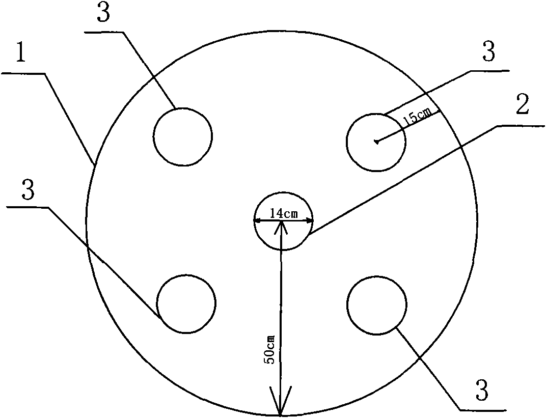
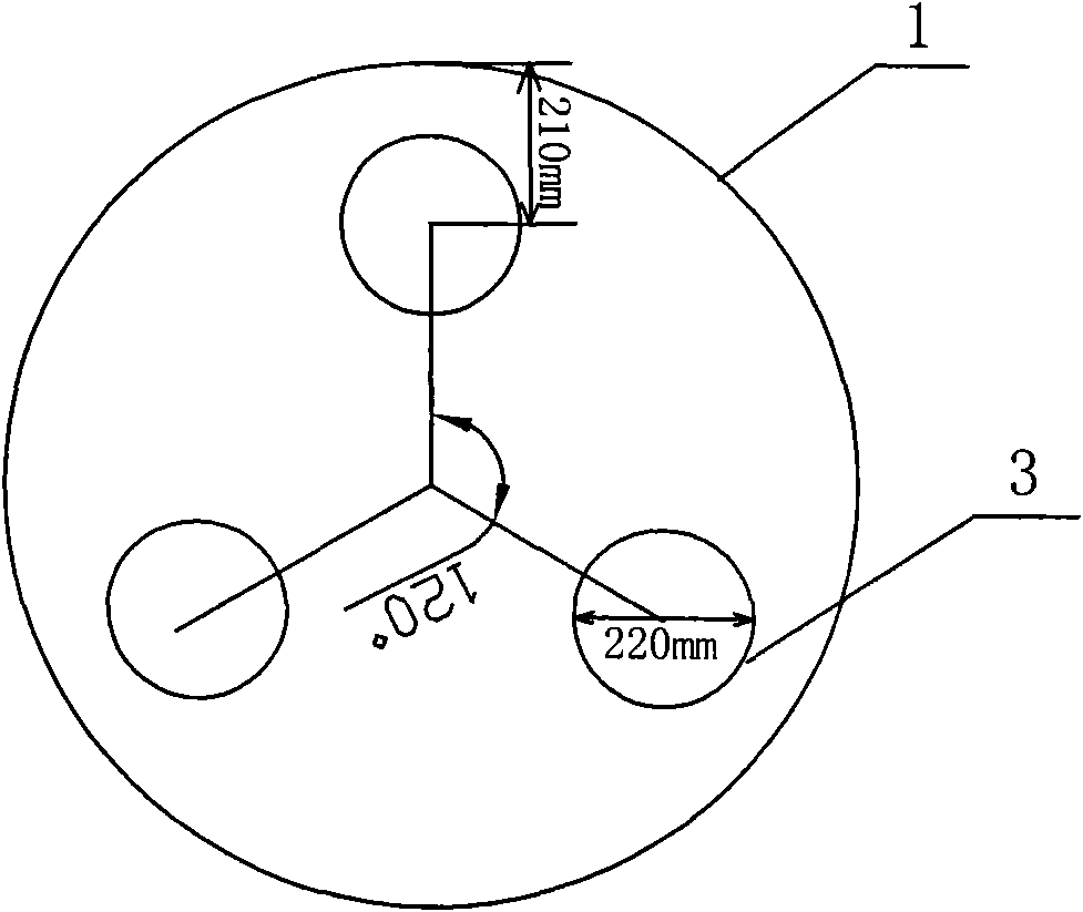
The invention relates to a rock mass pile foundation pore-forming preboring construction method, including: five hole sites are arranged at a drilled pile site, a center hole sit is arranged in the center of the drilled pile site, four surrounding hole sites are evenly distributed outside the center hole site, the distance between the center of each surrounding hole and the margin of the drilled hole site is equal, and an in-the-hole drill with a drill model number of Phi 140mm is used for drilling on the center hole site and the surrounding hole site. Another hole distribution mode includes:three hole sites are arranged at the drilled pile site, the distance between the center of each hole site and the center of the drilled hole pile site is equal and the connection lines of two adjacenthole site and the center form a 120 degrees angle, the distance between the center of the hole site and the margin of the drilled hole pile site is equal, and an in-the-hole drill with the model number of Phi 220mm is used for punching on the hole site. The method of the invention realizes that pore-forming efficiency of a punching drill is high, slant rock correction difficulty is reduced, construction quality is high, construction period is short and construction cost is low when rock bearing capacity at the foundation pile site of a bridge pile is more than 1000kPa or a slant rock is existed.
Description
Pre-drilling Construction Method for Hole Forming of Rock Mass Pile Foundation technical field The invention relates to a bridge pile construction method, in particular to a rock mass pile foundation hole pre-drilling construction method, and belongs to the technical field of bridge pile foundation construction. Background technique In the engineering construction of railways, highways and municipal bridges, it is inevitable to encounter pile foundations on the rock mass. In order to ensure the firmness, safety and stability of the pile foundations, the prior art method is mainly to use percussion drills for construction. The hole-forming principle is: use a drilling rig to drill holes. The steps are to lift the drill bit to a certain height through other mechanical equipment, use the drill bit's own weight to crush the rock, and then use the mud to float the gravel, and finally the mud and mud are pumped by the mud pump. The mixture of gravel is pumped out of the hole. W...
Claims
Login to View More Application Information
Patent Timeline
 Patent Type & Authority Patents(China)
IPC IPC(8): E02D27/12E21B1/00
Inventor 郝长福罗卿曹宝军赵靓
Owner SINOHYDRO ENG BUREAU 4
Features
- R&D
- Intellectual Property
- Life Sciences
- Materials
- Tech Scout
- Unparalleled Data Quality
- Higher Quality Content
- 60% Fewer Hallucinations
Learn More Browse by: Latest US Patents, China's latest patents, Technical Efficacy Thesaurus, Application Domain, Technology Topic, Popular Technical Reports.
© 2025 PatSnap. All rights reserved.Legal|Privacy policy|Modern Slavery Act Transparency Statement|Sitemap|About US| Contact US: help@patsnap.com