

Air floatation conveyance device and method of conveyance using air
A technology of conveying device and conveying direction, which is applied in the direction of transportation and packaging, conveyors, conveyor objects, etc., to achieve the effects of increasing air pressure, reducing manufacturing costs, and suppressing escape
- Summary
- Abstract
- Description
- Claims
- Application Information
AI Technical Summary
Problems solved by technology
Method used
Image

Examples
no. 1 example
[0094] Fig. 1 is a diagram showing a structural example of the first embodiment of the air lift transportation device of the present invention.
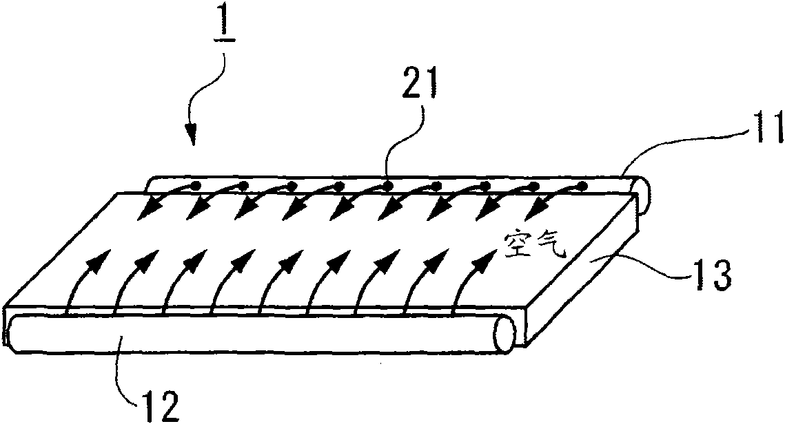
[0095] Figure 1A It is a figure which shows the example of the air lift unit 1 which becomes a constituent unit of the air lift conveyance apparatus of this invention.
[0096] Such as Figure 1A As shown, the air lift unit 1 is provided with a pair of air supply pipes 11 , 12 on both sides of the back panel 13 . Compressed air is supplied to the air supply pipes 11 and 12 .
[0097] The air supply pipes 11 and 12 are provided with oblique nozzles 21 , and are configured to eject air obliquely upward from the rear panel 13 as indicated by arrows.
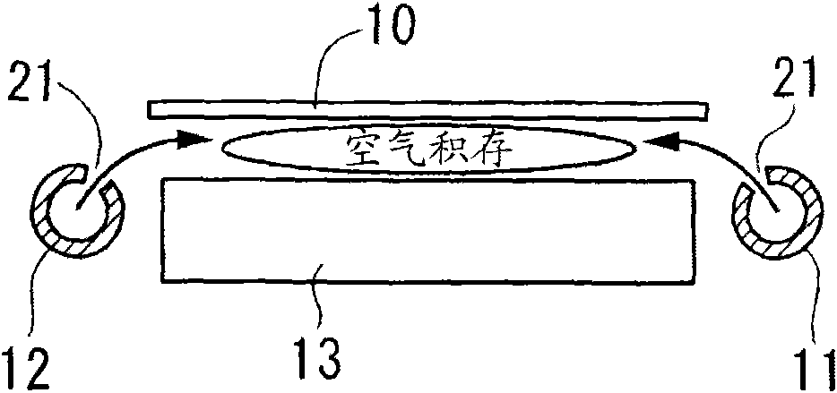
[0098] And if Figure 1B As shown, air is jetted obliquely upward from the rear plate 13 from the inclined nozzle 21 to form an air pool between the planar substrate 10 to be transported and the back plate 13 , and the planar substrate 10 is lifted from the back plate 13 .
[0099] ...
no. 2 example
[0102] Figure 2 and image 3 It is a figure which shows the structure example of the 2nd embodiment of the air lift transportation apparatus of this invention.
[0103] Figure 2A It is a figure which shows the structural example of the air lift unit 2 in 2nd Example of an air lift conveyance apparatus.
[0104] Figure 2A The air lift unit 2 shown is in Figure 1A In the shown air lift unit 1 , an air supply pipe 31 is added to the front side of the back plate 13 (downstream side in the transport direction of the flat substrate). The air supply pipe 31 is provided with an inclined nozzle 32, such as Figure 2B As shown, when the rigidity of the planar substrate 10 is small and a drooping portion 10a is generated at the front end of the planar substrate 10, the drooping portion 10a at the front end of the planar substrate 10 is lifted upward by jetting air from the inclined nozzle 32 obliquely above the rear plate 13. stand up.
[0105] Thus, if Figure 2C As shown, whe...
no. 3 example
[0109] Figure 4 and Figure 5 It is a figure which shows the structure example of the 3rd embodiment of the air lift transportation apparatus of this invention.
[0110] Figure 4A It is a figure which shows the structural example of the air lift unit 2 in the air lift conveyance apparatus 3rd Example.
[0111] Figure 4A The air lift unit 2 shown is in Figure 1A Air supply pipes 31 and 31-1 are added to the front side and rear side (downstream side and upstream side in the transport direction of the flat substrate) of the rear panel 13 of the air lift unit 1 shown. The air supply pipes 31 and 31-1 are provided with inclined nozzles 32 and 32-1, as Figure 4B As shown, when the rigidity of the planar substrate 10 is small and a drooping portion 10a occurs at the front end of the planar substrate 10, the drooping portion 10a at the front end of the planar substrate 10 is lifted upward by jetting air from the inclined nozzle 32-1 obliquely above the rear plate 13. Fang lif...
PUM
 Abstract
Description
Claims
Application Information