

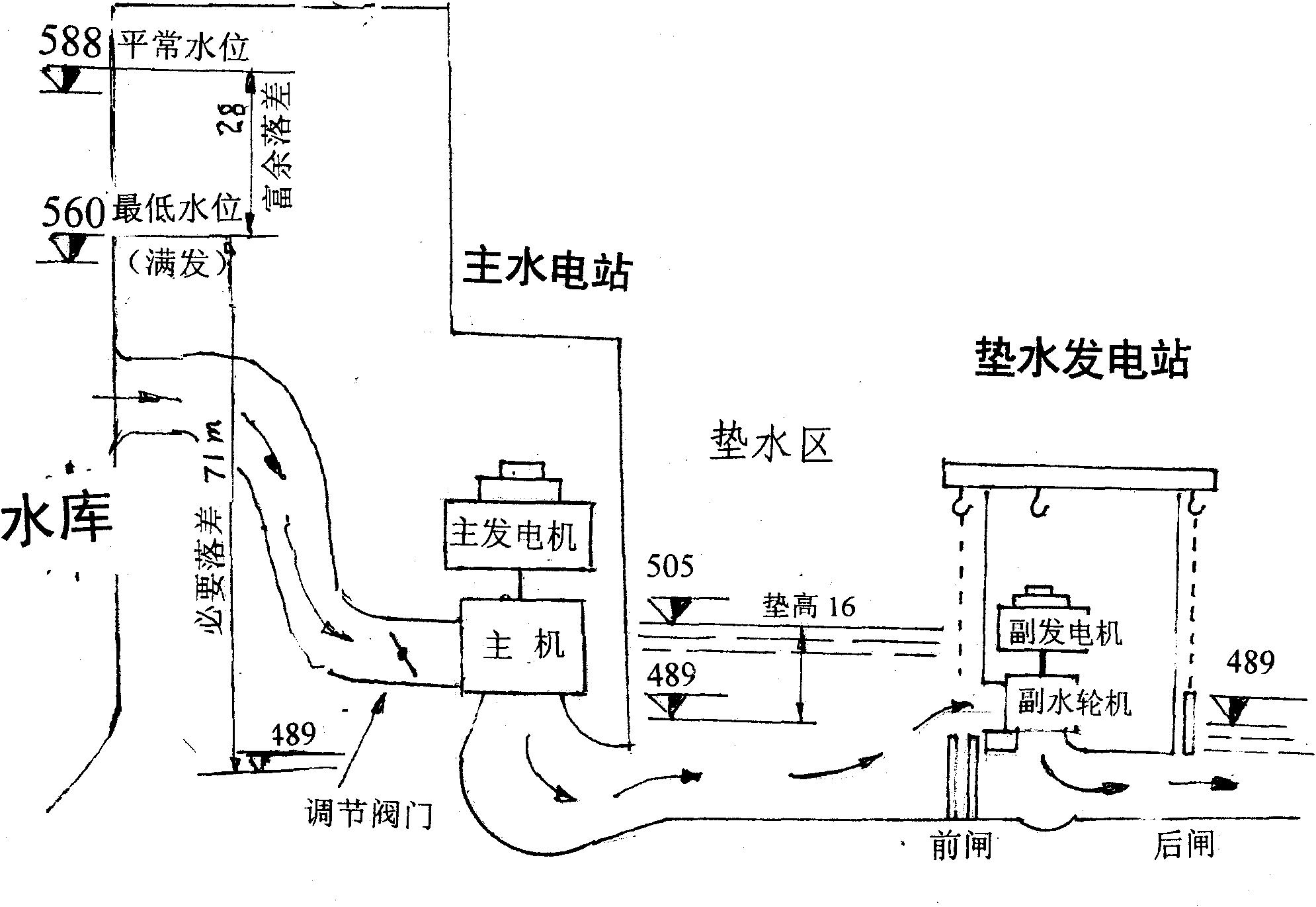
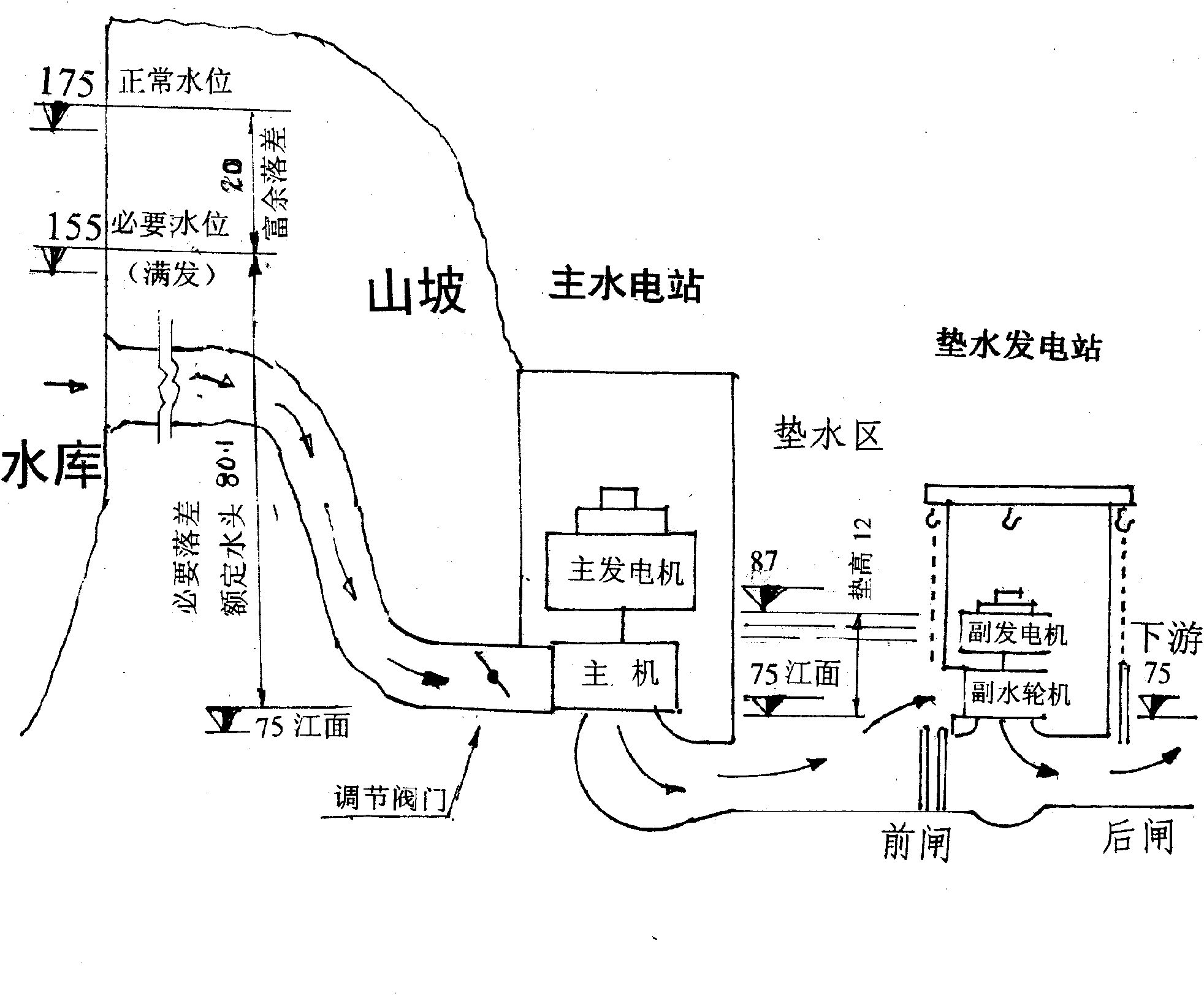
Water-filling power station
A technology of reservoirs and water wheels, which can be used in hydroelectric power stations, hydroelectric power generation, traditional hydroelectric energy, etc., and can solve problems such as large surplus and drop.
- Summary
- Abstract
- Description
- Claims
- Application Information
AI Technical Summary
Problems solved by technology
Method used
Image

Examples
Embodiment Construction
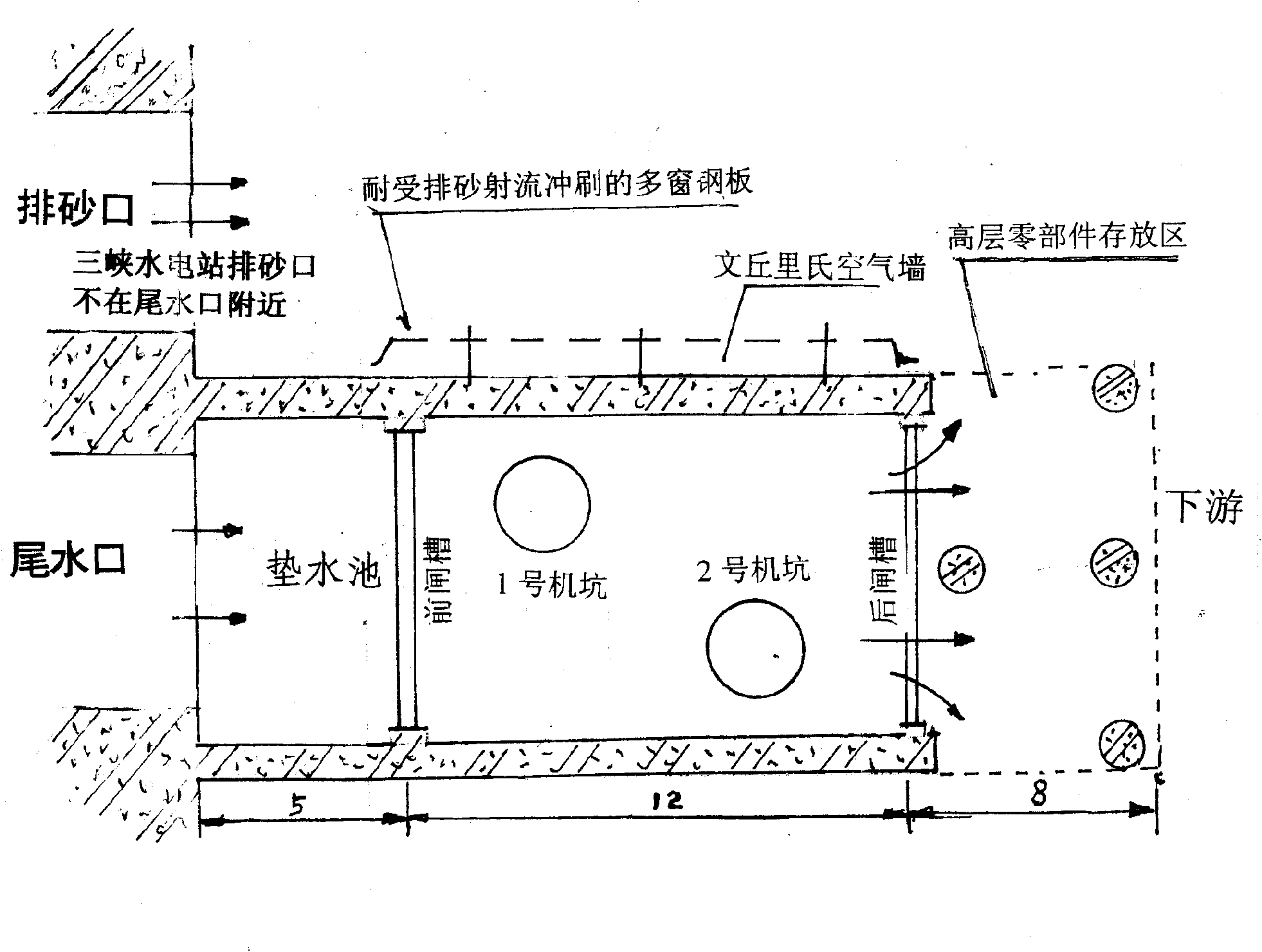
[0082] 1. Water padding wall: the task is to pad up the tail water of the turbine to supply the auxiliary machine to generate electricity. The construction work will not affect the power generation of the main engine.
[0083] 1. In order to occupy less space in the tailrace, a thin wall with tension bars is used. The left wall and the right wall ride on the tailpipe.
[0084] 2. Build a construction platform on the tailrace and install a large-diameter drilling rig. Rows of holes with a diameter of 80-100 cm are drilled at the foundation of the wall and penetrate into the rock at the foot of the dam.
[0085] 3. Insert the prefabricated pipe sleeve into the bottom of the hole, then insert the existing steel cage into the pipe sleeve and pour concrete to form an underwater row of piles, which are exposed to the water surface.
[0086] 4. Lay guard plates between rows of piles, insert steel cages, pour concrete, and expose the water surface to form underwater thin walls. Th...
PUM
 Abstract
Description
Claims
Application Information