
High-pressure jet grouting enlarged footing anchor rod and construction method thereof

A technology of high-pressure rotary grouting and construction methods, which is applied in the direction of excavation, foundation structure engineering, and sheet pile walls, etc., and can solve the problem of not being able to improve the pull-out force of the anchor rod, affecting the pull-out force and quality of the anchor rod, and the pull-out force of the anchor rod No advanced problems, good construction effect, simple construction method and wide application range

Active Publication Date: 2010-10-20
陕西中机岩土工程有限责任公司
View PDF0 Cites 0 Cited by
  • Summary
  • Abstract
  • Description
  • Claims
  • Application Information

AI Technical Summary

Problems solved by technology

The disadvantage of the auger drilling method is that it is generally impossible to form an enlarged body at the local and bottom, so the pulling force of the anchor is not high, and sometimes shrinkage and collapse will occur, which further affects the pulling force and quality
For sand layers, mud circulation drilling is generally used to form holes, but during the construction process, due to the influence of mud, the pull-out force of the bolt is greatly reduced, and it is also impossible to form a local and bottom enlargement that increases the pull-out force of the bolt.
In addition, the soil or mud discharged by the above two methods will also cause certain adverse effects on the environment.

Method used


Image

  • High-pressure jet grouting enlarged footing anchor rod and construction method thereof
  • High-pressure jet grouting enlarged footing anchor rod and construction method thereof
  • High-pressure jet grouting enlarged footing anchor rod and construction method thereof

Examples


Embodiment 1

[0043] Such as Figure 6 As shown, the high-pressure rotary spraying expansion head bolt described in the present invention includes a bolt body and a local expansion head 9 arranged in the middle of the bolt body and / or a bottom enlargement head 10 arranged at the bottom of the bolt body, The number of said local enlargement heads 9 is one or more. In this embodiment, the middle part of the anchor body is provided with a local expansion head 9 and the number of the local expansion head 9 is one, and the bottom of the anchor body is provided with a bottom expansion head 10 .

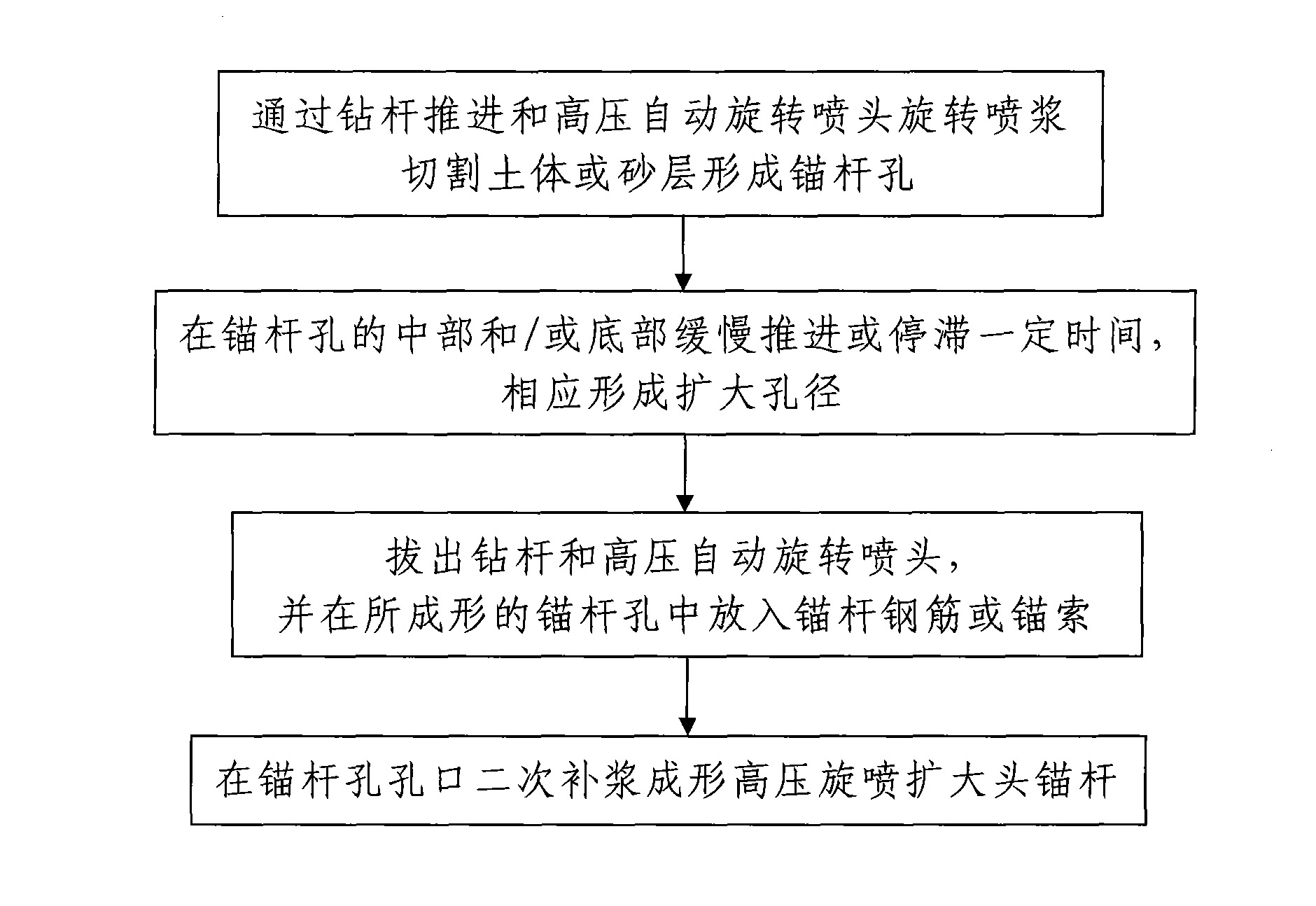
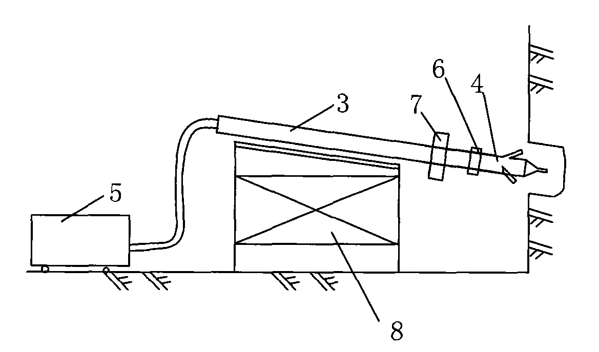
[0044] Such as figure 1 , figure 2 and image 3 As shown, the construction method of the above-mentioned high-pressure rotary spraying expansion head anchor rod includes the following steps:

[0045] Step 1, the bolt body is hole-forming construction, and the construction process is as follows:

[0046] 101. A high-pressure automatic rotary sprinkler 4 is coaxially sealed and installed at the front...

Embodiment 2

[0059] Such as Figure 7 As shown, in this embodiment, the difference from Embodiment 1 is that the formed high-pressure rotary spraying expansion head anchor rod includes an anchor rod body and a local expansion head 9 arranged in the middle of the anchor rod body, and the local The quantity of the enlarged head 9 is one, that is to say, the bottom of the formed anchor body is not provided with a bottom enlarged head 10 .

[0060] Correspondingly, in this embodiment, the construction method of the high-pressure rotary spraying expanding head bolt is different from that in Example 1 in that: in step 2, during the forward advancement of the drill pipe 3 and the high-pressure automatic rotary nozzle 4, When the two advance to the design position of the local expansion body 2 (i.e. the design depth of the local expansion head on the pre-determined anchor rod body), specifically advance to the design position or reach the design position, correspondingly slowly advance or Stand s...

Embodiment 3

[0062] Such as Figure 8 As shown, in this embodiment, the difference from Embodiment 1 is that the formed high-pressure rotary spraying expansion head anchor rod includes an anchor rod body and a bottom expansion head 10 arranged at the bottom of the anchor rod body, that is to say, The formed bolt body is not provided with a local enlarged head 9 in the middle.

[0063] Correspondingly, in this embodiment, the construction method of the high-pressure rotary spraying expanding head bolt is different from that in Example 1 in that: in step 2, during the forward advancement of the drill pipe 3 and the high-pressure automatic rotary nozzle 4, When the drill pipe 3 and the high-pressure automatic rotating nozzle 4 are pushed forward to the design depth of the bolt body, specifically to the design depth or to the design depth, they will be pushed forward slowly or stagnant for a period of time, so that The high-pressure automatic rotating nozzle 4 rotates continuously for a long ...


PUM


Abstract

The invention discloses a high-pressure jet grouting enlarged footing anchor rod and a construction method thereof. The anchor rod comprises an anchor rod body and a partial enlarged footing and / or a bottom enlarged footing which are arranged on the anchor rod body. The construction method comprises the following steps: firstly, cutting a soil body or a sand layer to form an anchor rod hole through the propulsion by a drilling rod and the rotary grouting by a high-pressure auto-rotating spray head; secondly, propelling slowly or stagnating for certain time at the middle part and / or the bottomof the anchor rod hole so as to form a partially enlarged aperture and / or a bottom enlarged aperture correspondingly; thirdly, pulling out the drilling rod and the high-pressure auto-rotating spray head, and putting an anchor rod reinforcing steel bar or an anchor cable in the formed anchor rod hole; and fourthly, performing secondary grouting at the orifice of the anchor rod hole to form the high-pressure jet grouting enlarged footing anchor rod. The construction method has the advantages of simple steps, low construction cost and good construction effect, and the formed high-pressure jet grouting enlarged footing anchor rod has the advantages of reasonable structure, large drawing force and low manufacturing cost.

Description

technical field [0001] The invention belongs to the technical field of foundation pit or slope support engineering such as construction, water conservancy, and highway, and in particular relates to a high-pressure rotary spraying expanding head bolt and a construction method thereof. Background technique [0002] In construction, water conservancy, highway and other foundation pit or slope support projects, anchor rods are commonly used support types, and the anchor rods used are usually formed by auger drilling or mud circulation drilling. The disadvantage of the auger drilling method is that it is generally impossible to form an enlarged body at the local and bottom, so the pulling force of the anchor is not high, and sometimes shrinkage and collapse will occur, which further affects the pulling force and quality. For the sand layer, mud circulation drilling is generally used to form holes, but during the construction process, the pull-out force of the bolt is greatly red...

Claims


Application Information

Patent Timeline
Patent Type & Authority Patents(China)
IPC IPC(8): E02D5/74E02D17/20E02D17/04
Inventor 张建山田树玉杨丽娜李哲
Owner 陕西中机岩土工程有限责任公司
Learn More