Bidirectional supercharging-type electric gas supercharging device

A gas supercharging, electric technology, applied in the direction of fluid pressure converter, mechanical equipment, etc., can solve the problems of limited application, small displacement of supercharger, low system efficiency, etc., and achieve the effect of reducing frequent start and stop

Inactive Publication Date: 2009-11-11
蔡茂林
View PDF0 Cites 7 Cited by
  • Summary
  • Abstract
  • Description
  • Claims
  • Application Information

AI Technical Summary

Problems solved by technology

However, the low-pressure gas on the driving side of the supercharger is directly discharged into the atmosphere, resulting in large energy loss and low system efficiency.
In addition, this type of supercharger has a sma

Method used


Image

  • Bidirectional supercharging-type electric gas supercharging device

Examples


Embodiment Construction

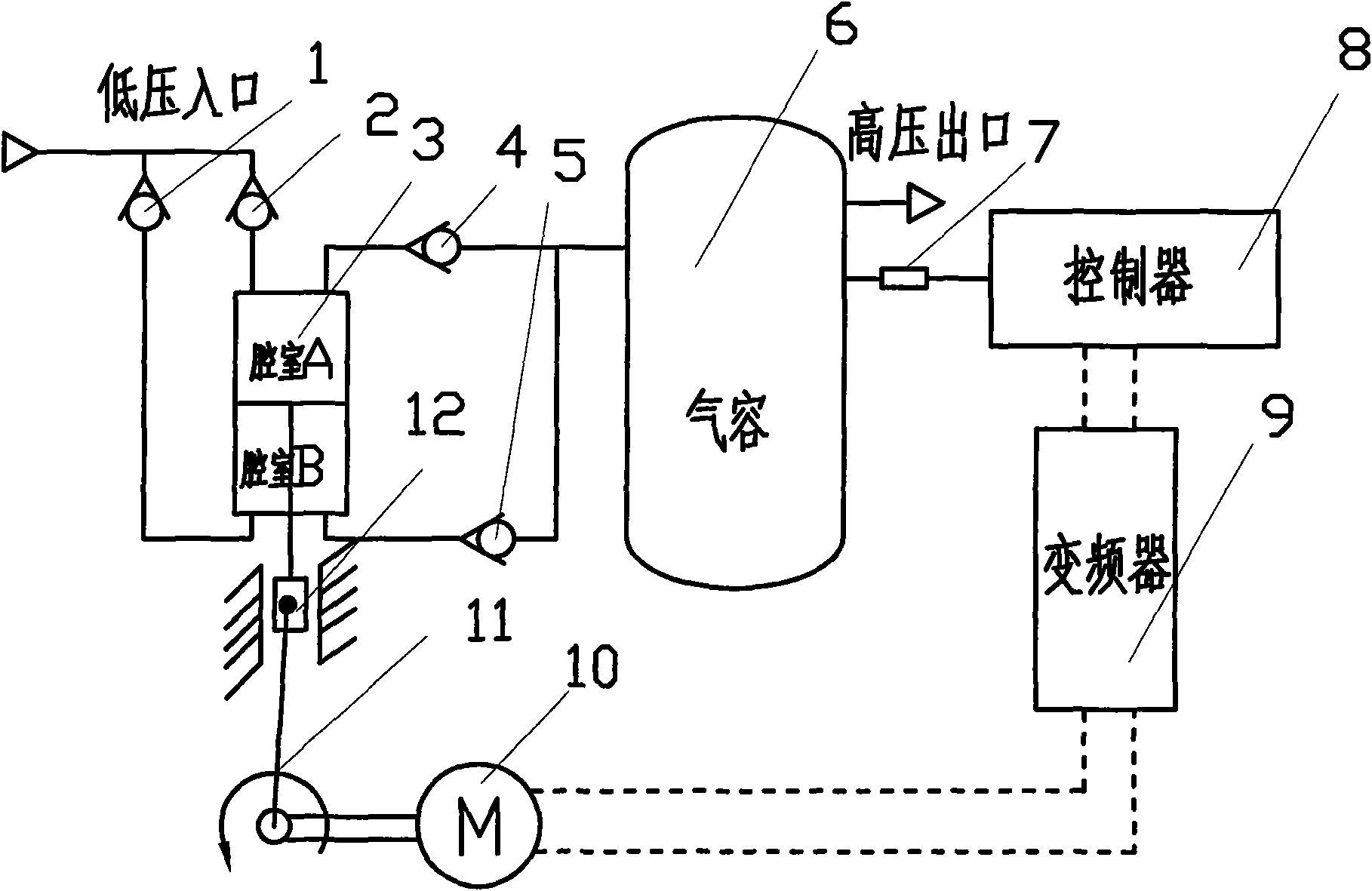
[0011] 1. The gas is filled into the chamber B of the cylinder (3) from the low-pressure gas source through the check valve (1) and the motor (10) drives the shaft (11), the piston pressurizes the gas in the chamber A, and the chamber A The medium-high pressure gas is charged into the gas container (6) through the one-way valve (4), and finally the high-pressure gas is output to the gas-consuming equipment. When the piston of the cylinder (3) reaches the upper end of the stroke, it is reversed under the action of the shaft (11), and the gas is filled into the chamber A from the low-pressure gas source through the one-way valve (2), and the motor (10) jointly drives the crankshaft (11) , the piston pressurizes the gas inside the chamber B of the cylinder (3), the high-pressure gas in the chamber B is filled into the gas container (6) through the check valve (5), and finally the high-pressure gas is output to the gas-consuming equipment. This is one working cycle of the supercha...


PUM


Abstract

The invention belongs to the energy-saving field of pneumatic system and realizes a bidirectional supercharging-type electric gas supercharging device. The supercharging device mainly relates to a gas supercharging technology which adopts combined driving of a motor and a low-pressure gas source. The pneumatic system with combined driving of the motor and the low-pressure gas source adopts a double-acting cylinder. When in use, the low-pressure source gas is fill in one side of a piston in the cylinder so as to push the piston and the motor to together drive the piston to compress the low-pressure air at the other side, thus realizing supercharging, sufficiently utilizing the energy of the low-pressure gas, and reducing the energy consumption of the motor. A frequency-conversion controller takes the pressure of the high-pressure gas as a target and adjusts the starting, running and stopping of the motor in real time, thus outputting stable pressure and reducing the frequent starting and stopping of the motor. Furthermore, the gas supercharging machine adopts the double-acting cylinder, thus having simple structure, small vibration and low noise.

Description

[0001] The invention belongs to the field of energy saving of pneumatic systems, and relates to a two-way supercharging electric gas supercharging device. Background technique [0002] Gas booster device is a key technology in the field of energy saving of pneumatic system. In pneumatic systems, certain occasions often require a small amount of locally high-pressure gas. For example: some or some devices in the gas circuit need to use high pressure; the pressure of the main gas circuit drops due to long-distance gas transmission or gas leakage, and the minimum operating pressure of the pneumatic device cannot be guaranteed; the space is narrow and large-caliber cylinders cannot be equipped, but the output force And have to make sure, and so on. To solve such problems, the local pressurization method is usually used at present, which uses a pressurization device to obtain high-pressure gas, which can save costs and reduce the pressure of the gas source, especially for energy-s...

Claims


Application Information

Patent Timeline
IPC IPC(8): F15B3/00
Inventor 石岩蔡茂林
Owner 蔡茂林
Why Eureka
Try Eureka