Split type spherical outer ring roller bearing

A spherical outer ring and roller bearing technology, applied in the field of bearings of rotating parts, can solve the problems of reduced bearing service life, damage to mechanical equipment, uneven bearing force, etc. uniform force effect

Inactive Publication Date: 2009-11-11
赵铁栓
View PDF0 Cites 1 Cited by
  • Summary
  • Abstract
  • Description
  • Claims
  • Application Information

AI Technical Summary

Problems solved by technology

The bearing capacity of the lower part of the bearing increases, while the bearing capacity of the upper part decreases, the force on the bearing is uneven, and the irregularly changing bearing capacity acts on the bearing, which accele

Method used


Image

  • Split type spherical outer ring roller bearing

Examples


Embodiment 1

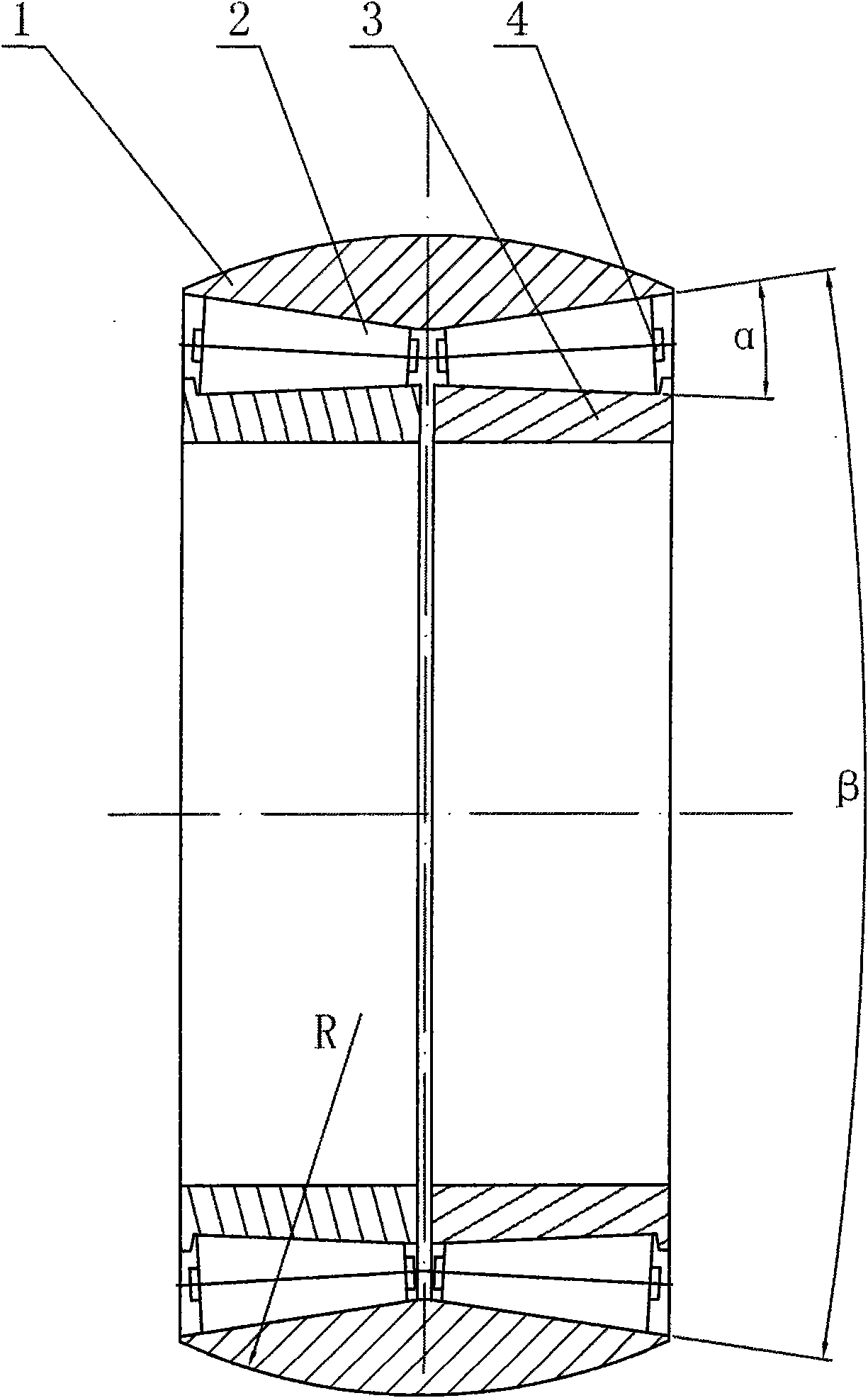
[0011] exist figure 1 Among them, the split spherical outer ring roller bearing of this embodiment is composed of a bearing outer ring 1, rollers 2, bearing inner ring 3, and a roller frame 4 connected.

[0012] Two bearing inner rings 3 are installed in the bearing outer ring 1. The outer surface of the bearing outer ring 1 is a spherical surface with a spherical radius R of 5000mm. The inner surface of the bearing outer ring 1 is a conical surface with a cone angle of β. The bearing inner ring The inner surface of 3 is a cylindrical surface, and the outer surface of bearing inner ring 3 is a conical surface, and the cone angle is α. The inner surface of the bearing outer ring 1 and the outer surface of the bearing inner ring 3 form two interconnected ring-shaped conical spaces. Two roller frames 4 are installed in the annular circular platform space between the inner surface of the bearing outer ring 1 and the outer surface of the bearing inner ring 3, and rollers 2 are ins...

Embodiment 2

[0014] In this embodiment, the outer surface of the bearing outer ring 1 is a spherical surface, the radius R of the spherical surface is 10mm, and the shape of the roller 2 is a truncated cone. The specific geometric shape of the roller can be determined by the conventional design in the mechanical design manual according to the bearing capacity. The specific number of columns 2 is determined according to the outer diameter of the inner ring 3 of the bearing. The specific data of the cone angle α of the outer surface of the bearing inner ring 3 and the specific data of the cone angle β of the inner surface of the bearing outer ring 1 are determined by the conventional design in the mechanical design manual according to the geometry of the roller. The geometric shapes of other components and the coupling relationship of the components are the same as those in Embodiment 1.

Embodiment 3

[0016] In this embodiment, the outer surface of the bearing outer ring 1 is a spherical surface, and the radius R of the spherical surface is 10000mm. The shape of the roller 2 is a truncated cone. The specific number of columns 2 is determined according to the outer diameter of the inner ring 3 of the bearing. The specific data of the cone angle α of the outer surface of the bearing inner ring 3 and the specific data of the cone angle β of the inner surface of the bearing outer ring 1 are determined by the conventional design in the mechanical design manual according to the geometry of the roller. The geometric shapes of other components and the coupling relationship of the components are the same as those in Embodiment 1.


PUM

PropertyMeasurementUnit
Spherical radiusaaaaaaaaaa

Abstract

The invention provides a split type spherical outer ring roller bearing. The inside of a bearing outer ring is provided with two bearing inner rings, and two roller racks in which rollers are arranged are arranged between the bearing outer ring and the two bearing inner rings; the outer surface of the bearing outer ring is spherical; and the roller racks are disconnected with the bearing outer ring and the bearing inner rings. For the split type spherical outer ring roller bearing adopting the structure, when the bearing axially swings, the bearing wholly swings, so that the rollers are evenly stressed, the bearing capacity is greatly improved, the bearing can be loaded with enough pre-tightening force when assembled, the bearing capacity applied on the bearing is even, and the service life of the bearing is prolonged. The bearing has the advantages of big bearing capacity, long service life and the like, and can be widely applied to rotary mechanical parts.

Description

technical field [0001] The invention belongs to the technical field of bearings for rotating parts, and in particular relates to a rolling contact bearing mainly used for radial load with two or more rows of rollers. Background technique [0002] Bearing is a component that converts sliding friction into rolling friction and plays a supporting role in the rotating body. It is widely used between the mating surfaces of various rotating mechanisms. [0003] At present, bearings are widely used and play a vital role in rotational motion. However, the bearing structure currently on the market is that the outer ring and the inner ring are integrated, so that when the bearing is applied to mechanical equipment with axial swing, the internal rollers of the bearing will partly detach from the track, resulting in a decrease in the bearing capacity of the bearing. At the same time, in order to maintain the flexible rotation of the bearing, a certain clearance should be maintained bet...

Claims


Application Information

Patent Timeline
IPC IPC(8): F16C19/38F16C33/36F16C33/48F16C33/58
Inventor 赵铁栓
Owner 赵铁栓
Why Eureka
Try Eureka