
Electromagnetic valve

A solenoid valve, valve seat technology, applied in the direction of lift valve, valve details, valve device, etc., can solve the problems of increasing the axial size of the valve seat 1a, material waste, poor operating performance, etc., to reduce the axial size, The effect of reducing manufacturing costs and reducing cumulative tolerances

Inactive Publication Date: 2009-11-11
ZHEJIANG SANHUA INTELLIGENT CONTROLS CO LTD
View PDF0 Cites 16 Cited by
  • Summary
  • Abstract
  • Description
  • Claims
  • Application Information

AI Technical Summary

Problems solved by technology

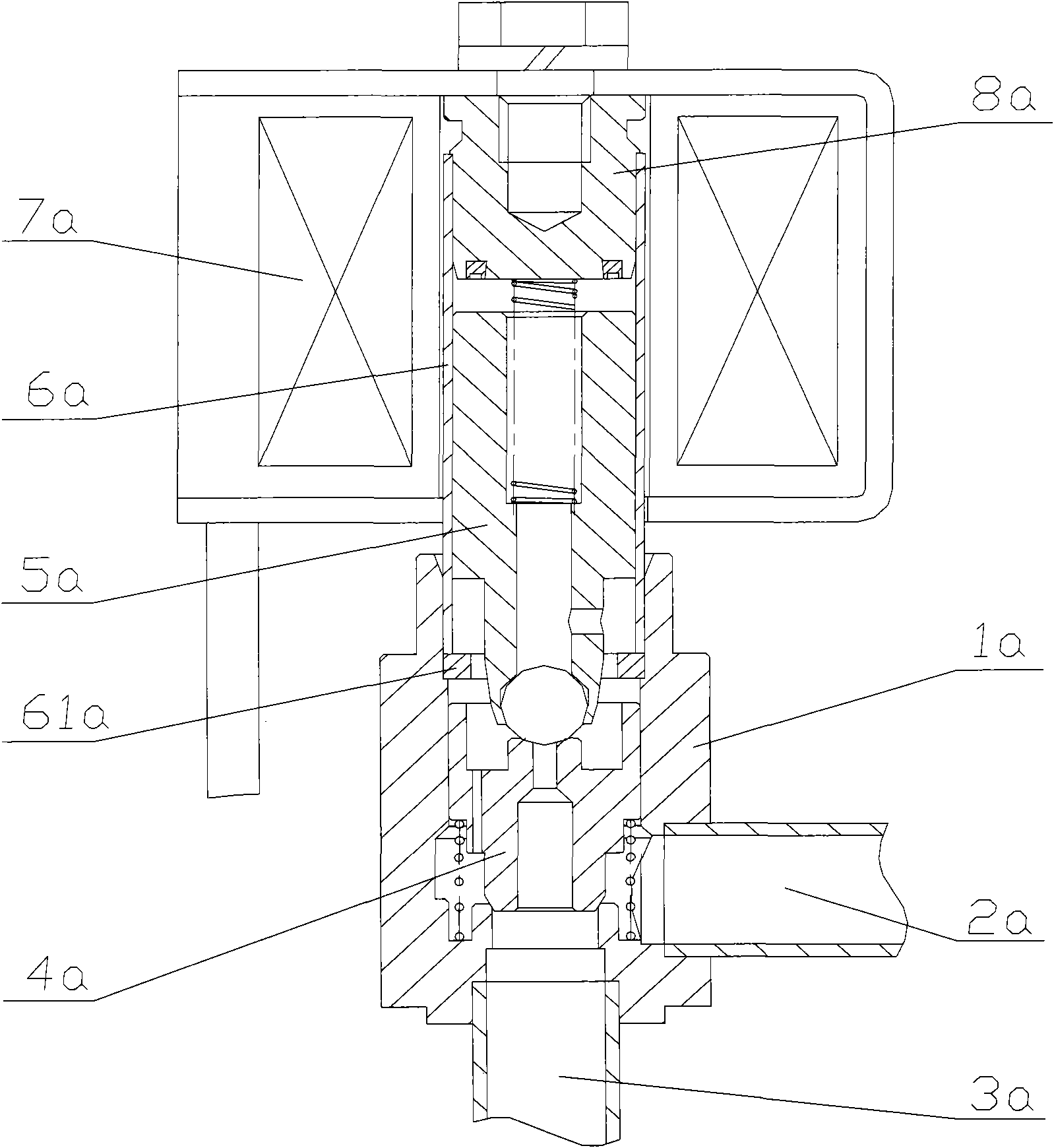
[0010] Since the stop ring 61a is a stamped part, the thickness tolerance of the stop ring 61a is relatively large, resulting in a large tolerance of the axial dimension of the sleeve 6a, plus the assembly tolerance with the sleeve 6a, which in turn affects the The consistency of the stroke of the moving iron core 5a will affect the consistency of the solenoid valve, and poor operating performance may occur
[0011] And, because the solenoid valve in the prior art, stop ring 61a is installed between sleeve pipe 6a and valve seat 1a, and stop ring 61a has certain thickness, thereby increased the axial dimension of valve seat 1a, Usually, the valve seat 1a is made of metallic copper material. It can be seen that increasing the axial dimension of the valve seat 1a will lead to waste of materials and lead to high manufacturing costs of the solenoid valve.

Method used


Image

  • Electromagnetic valve
  • Electromagnetic valve
  • Electromagnetic valve

Examples


Embodiment Construction

[0031] In order to enable those skilled in the art to better understand the technical solutions of the present invention, the present invention will be further described in detail below in conjunction with the accompanying drawings and specific embodiments.

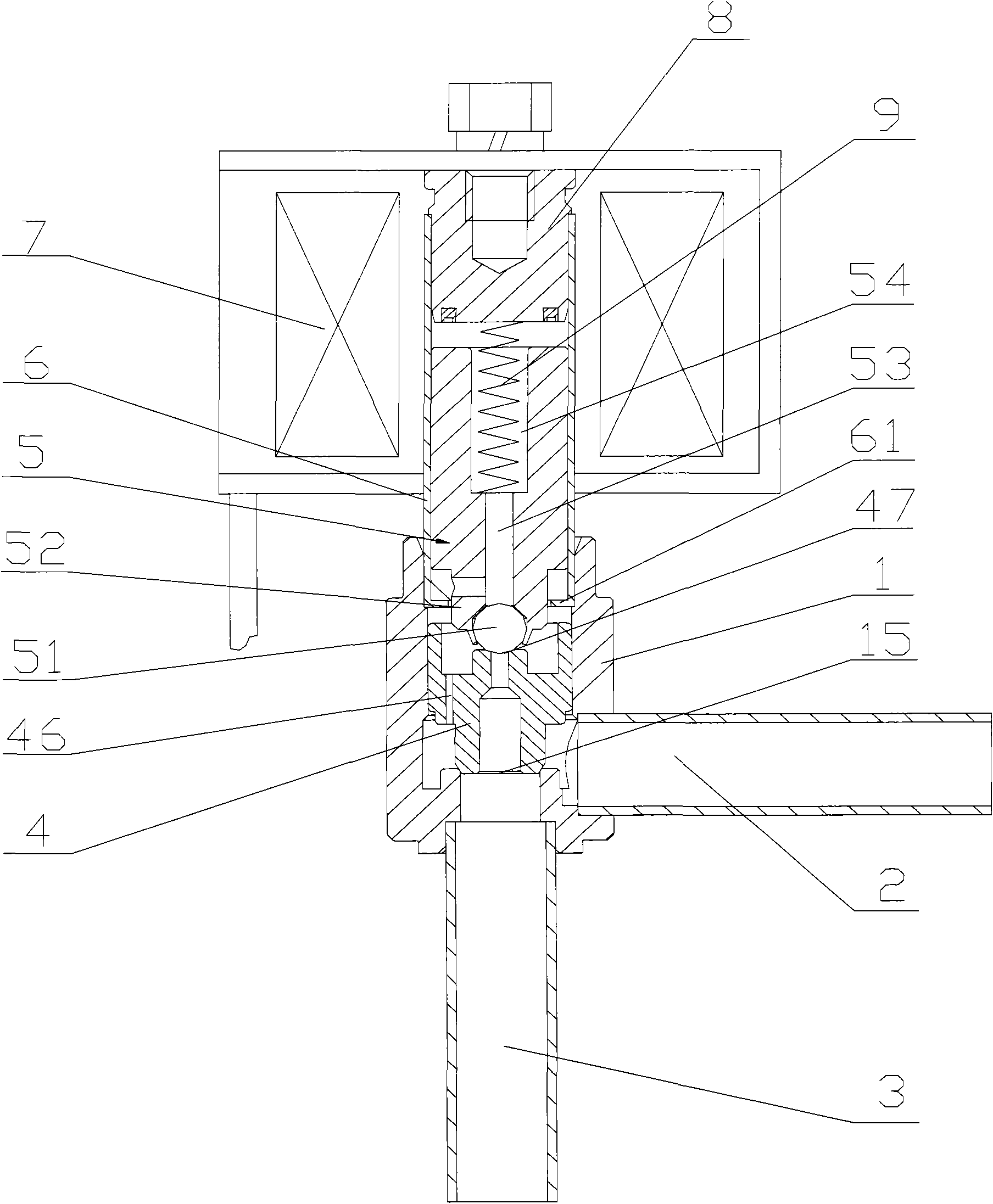
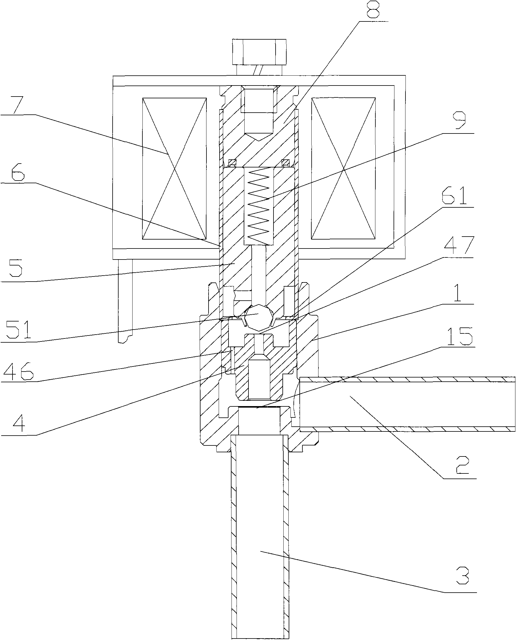
[0032] refer to figure 2 with image 3 , figure 2 It is a structural schematic diagram of a specific embodiment of the electromagnetic valve of the present invention in the closed state of the piston valve port; image 3 for figure 2 Schematic diagram of the structure of the electromagnetic valve in the open state of the piston valve port.

[0033] Such as figure 2 with image 3 As shown, the solenoid valve provided in this embodiment includes a valve seat 1 , a moving iron core 5 , a static iron core 8 , a sleeve 6 , a piston 4 , a coil 7 and a spring 9 .

[0034] An outlet pipe 3 is welded and fixed at one end of the valve seat 1 , an inlet pipe 2 is welded and fixed on the side wall of the valve seat 1 , and ...


PUM


Abstract

The invention discloses an electromagnetic valve which comprises a valve seat with an internal cavity, a piston that can axially move in the internal cavity of the valve seat, a guide sleeve connected with one end of the valve seat, a fixed iron core matched with the guide sleeve, a movable iron core that can axially reciprocate in the guide sleeve, and a spring positioned between the fixed iron core and the movable iron core in the guide sleeve, wherein the valve seat is provided with a main valve port and the fixed iron core is fixedly connected with the guide sleeve. The electromagnetic valve is characterized in that one end of the guide sleeve is used for fixing the fixed iron core is provided with an opening, and the other end is provided with a limit bottom surface positioning the piston, and the limit bottom surface is provided with a through hole used for leading the lower end part of the front end of the movable iron core to pass through. Because the guide sleeve is provided with the limit bottom surface, and one part is reduced from the electromagnetic valve, the stack tolerance of the axial size of the electromagnetic valve is reduced, and the electromagnetic valve has good action property, simple assembly and low manufacture cost.

Description

technical field [0001] The invention relates to a solenoid valve for control, in particular to a solenoid valve used in a refrigeration system. Background technique [0002] In the refrigeration system, the application of the solenoid valve has been very common. The solenoid valve can automatically control the on-off of the heat exchange medium (such as refrigerant) in the refrigeration system or change the flow direction of the heat exchange medium. [0003] refer to figure 1 , figure 1 It is a structural schematic diagram of a solenoid valve in the prior art. [0004] Such as figure 1 As shown, the solenoid valve includes a valve seat 1a, an inlet pipe 2a, an outlet pipe 3a, a piston 4a, a moving iron core 5a, a static iron core 8a, a coil 7a, a sleeve 6a and a stop ring 61a. [0005] The valve seat 1a is a hollow structure, one end of which is connected to the casing 6a, and the other end is connected to the outlet pipe 3a. The side wall of the valve seat 1a has an in...

Claims


Application Information

Patent Timeline
Patent Type & Authority Applications(China)
IPC IPC(8): F16K31/06F16K1/36F16K1/34F25B41/04
Inventor 严卫林
Owner ZHEJIANG SANHUA INTELLIGENT CONTROLS CO LTD
Learn More