
Tube furnace burner

A technology of burners and tube furnaces, applied in the direction of burners, gas fuel burners, combustion methods, etc., can solve the problems of harsh operating conditions, high energy consumption of tube furnaces, pollution of combustion products, etc., and achieve strong flame rigidity, The effect of stable and reliable combustion and wide application range

Inactive Publication Date: 2009-11-11
ACRE AUTOMATION CO LTD MCC
View PDF0 Cites 5 Cited by
  • Summary
  • Abstract
  • Description
  • Claims
  • Application Information

AI Technical Summary

Problems solved by technology

[0009] (4) Tube furnaces usually operate under high temperature and high pressure conditions, and the operating conditions are harsh
The energy consumption of the tube furnace is very high, and the noise pollution caused by the combustion process and the pollution of the combustion products are also very serious. The noise of the tube furnace mainly comes from the burner

Method used


Image

  • Tube furnace burner

Examples


Embodiment Construction

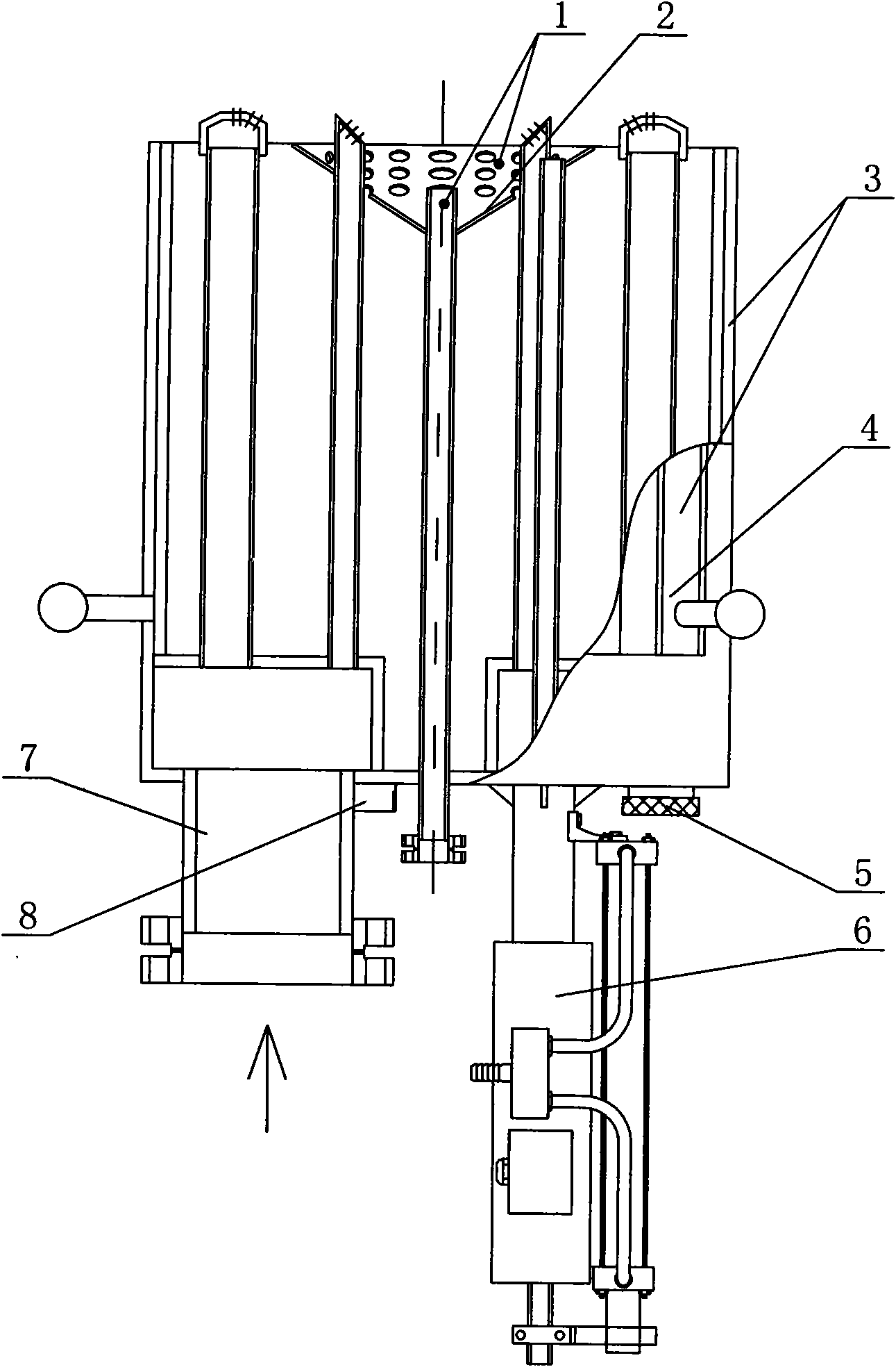
[0027] See figure 1 , tube furnace burner, including ignition nozzle 1, stable combustion cover 2, outer wall 3, regulating damper 4, fire viewing hole 5, pneumatic propeller 6, intake pipe group 7, fire detection installation pipe 8, and the upper part of the burner There is an ignition nozzle 1 and a stable combustion cover 2, the lower part is provided with an intake pipe group 7 and a pneumatic propeller 6, and the outer wall 3 is provided with an adjustable damper 4 that can adjust the air intake. The bottom of the burner is provided with a fire detection installation pipe 8 and a fire viewing hole 5 .

[0028] The functions of each component of the tube furnace burner are described as follows:

[0029] Regulating damper 4: mainly used to adjust the air distribution volume;

[0030] Pneumatic thruster 6: used to advance and retreat the ignition gun, advance the ignition gun when igniting, and withdraw the ignition gun after ignition, which effectively protects the ignit...


PUM


Abstract

The invention relates to a structure of a burner, in particular to a tube furnace burner. The tube furnace burner comprises an outer wall, an air inlet tube bank, an air inlet and an ignition tip, wherein a regulating door for regulating the air inlet amount is arranged on the outer wall; a pneumatic propeller is arranged at the bottom of the burner; a burning stabilizing cover is arranged at the top of the burner; a flame detection mounting pipe is arranged at the bottom or the side of the burner; and a flame viewing hole is also arranged at the bottom of the burner. The invention has the advantages of compact structure, stable burning, large regulation ratio, low noise, good flame spreadability, complete burning and easy control of burning and can be internally provided with a burning torch and a flame detection alarm system. The invention meets the current requirement on environmental protection, better saves the fuel and improves the burning efficiency.

Description

technical field [0001] The invention relates to a burner structure, in particular to a tube furnace burner. Background technique [0002] Tube heating furnace is a kind of thermal heating equipment. It uses the high-temperature flame and flue gas generated when the fuel is burned in the furnace as a heat source to heat the medium flowing at high speed in the furnace tube to make it reach the temperature specified by the process to supply the medium. The heat required in the process of fractionation, cracking or reaction ensures normal production. Compared with other heating methods, the main advantages of tubular heating furnace are high heating temperature (up to 1273K), large heat transfer capacity and easy operation and management. [0003] Tube furnaces play a pivotal role in petrochemical plants, and the energy consumption of tube furnaces is high. The energy consumption of the tube furnace accounts for about 80% to 90% of the production equipment. Its investment gen...

Claims


Application Information

Patent Timeline
Patent Type & Authority Applications(China)
IPC IPC(8): F23D14/00F23D14/36F23D14/26F23D14/46
Inventor 王常海叶煌徐海平金家影李刚孙虹于涛单永丰许波何鸥周浩张超杜建何忠海
Owner ACRE AUTOMATION CO LTD MCC
Learn More