
Water heater with heating-supply from transcritical carbon dioxide heat-pump

A carbon dioxide, transcritical technology, applied in hot water central heating systems, household heating, heating methods, etc., can solve the problems of water temperature limitation, low heat pump energy efficiency ratio, destruction of ozone layer greenhouse benefits, etc., to improve efficiency and EER. Effect

Inactive Publication Date: 2009-11-11
UNIV OF SHANGHAI FOR SCI & TECH
View PDF0 Cites 18 Cited by
  • Summary
  • Abstract
  • Description
  • Claims
  • Application Information

AI Technical Summary

Problems solved by technology

Fuel water heaters are mainly gas-based. This type of water heater emits a large amount of exhaust gas during use. In addition to carbon dioxide, there is also carbon monoxide, a product of incomplete combustion in the exhaust gas, which is prone to poisoning accidents.
Electric water heaters waste a lot of electric energy. Although electric water heaters are equipped with leakage protection, electric shock accidents occur from time to time when using electric water heaters.
Solar water heaters are environmentally friendly and energy-saving products, but they are greatly affected by the weather, and the area and time of use are greatly restricted.
In addition, there are heat pump water heaters on the market, but the working fluids of these heat pump water heaters are generally traditional working fluids such as R22 and R410A, which will not only destroy the ozone layer but also bring greenhouse benefits, and these working fluids must produce hot water above 60 °C The exhaust pressure of the compressor will be too high and the energy efficiency ratio (EER) of the heat pump will be too low, so the water temperature will be limited

Method used


Image

  • Water heater with heating-supply from transcritical carbon dioxide heat-pump

Examples


Embodiment Construction

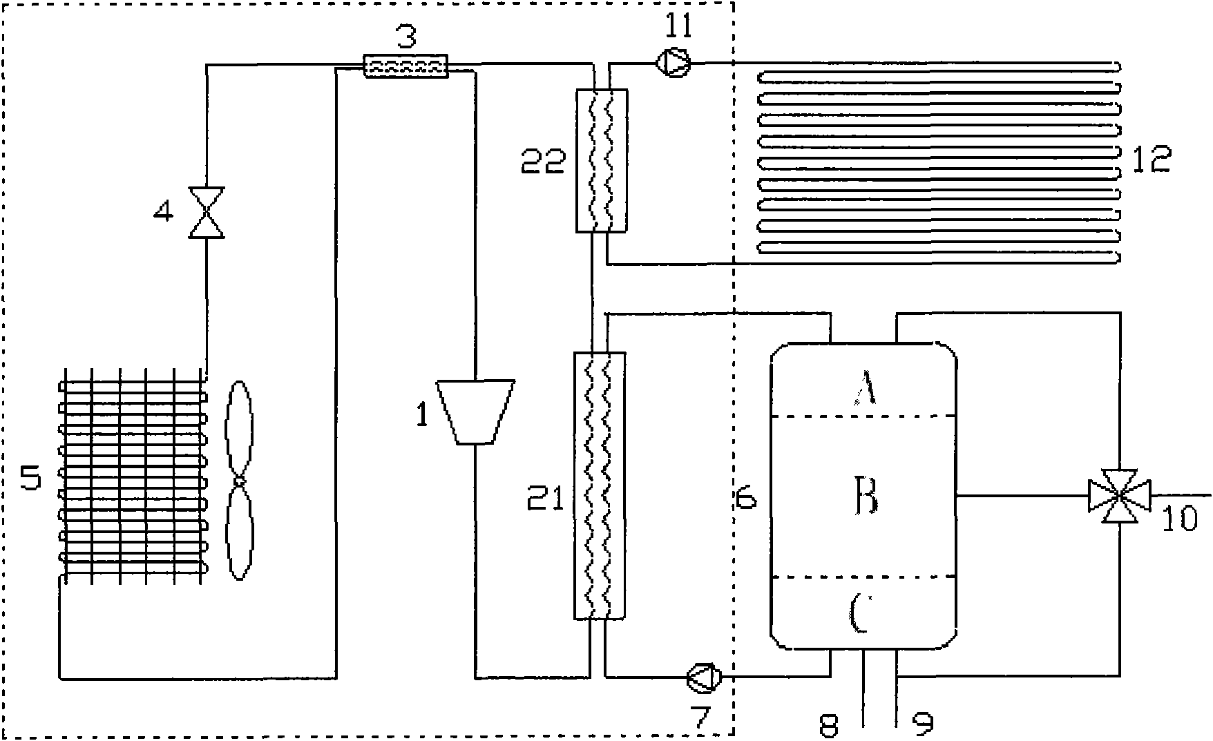
[0021] Attached below figure 1 The present invention is further described.

[0022] Such as figure 1 As shown, a transcritical carbon dioxide heat pump heating water heater includes three parts: a transcritical carbon dioxide heat pump system, a hot water supply system and a heating circulation system.

[0023] Wherein, the transcritical carbon dioxide heat pump system absorbs heat from the outside and provides it to the hot water supply system and the heating system, which includes a compressor 1, a first air cooler 21, and a second air cooler 22 sequentially located on the first circulation pipeline , regenerator 3, expansion valve 4, evaporator 5, regenerator 3;

[0024] Among them, the heat exchangers of the first air cooler 21 and the second air cooler 22 adopt the shell-and-tube type, and the evaporator 3 adopts a plate-fin heat exchanger, and the heat exchange of the evaporator 5 is enhanced by a fan;

[0025] The working fluid used in the transcritical carbon dioxid...


PUM


Abstract

A water heater with heating-supply from a transcritical carbon dioxide heat-pump comprises a transcritical carbon dioxide heat-pump system, a hot-water supply system and a heating circulation system. The transcrtical carbon dioxide heat-pump system comprises a compressor, a first gas cooler, a second gas cooler, a heat regenerator, an expansion valve, an evaporator and the other heat regenerator which are sequentially positioned on a first circulation pipeline; the hot-water supply system comprises a water tank, a first pump and a hot water outlet valve, wherein the water tank comprises a high-temperature zone A, an intermediate-temperature zone B and a low-temperature zone C; and the heating circulation system comprises a second gas cooler, a second pump and end equipments which are positioned on a second circulation pipeline. The invention reduces the temperature of dioxide carbon at the inlet of the expansion valve and respectively raises the superheat degree of dioxide carbon at the inlet of the compressor and EER of heat-pump circulation so as to ensure the lower temperature of water entering the gas cooler from the water tank; the reduction of the temperature of the first gas cooler enhances the efficiency of the heat-pump system; and both high-temperature water and intermediate-temperature water can be provided according to requirement of users.

Description

technical field [0001] The invention belongs to the field of heat pump water heaters, and in particular relates to a water heater device using a transcritical carbon dioxide heat pump to supply hot water and heat. Background technique [0002] With the improvement of people's living standards, water heaters have been popularized as a household appliance, and people's demand for hot water is increasing, and the energy consumption of water heaters is getting higher and higher. There are currently three types of traditional water heaters on the market: fuel water heaters, electric water heaters and solar water heaters. Fuel water heaters are mainly gas-based. This type of water heater emits a large amount of exhaust gas during use. In addition to carbon dioxide, there is also carbon monoxide, a product of incomplete combustion in the exhaust gas, which is prone to poisoning accidents. Electric water heaters are a big waste of electric energy. Although electric water heaters ar...

Claims


Application Information

Patent Timeline
Patent Type & Authority Applications(China)
IPC IPC(8): F24D3/18F24D3/08F24D3/02F24D3/12F24D19/08
CPCY02B30/12
Inventor 吕静杨大章于国清何哲彬黄秀芝
Owner UNIV OF SHANGHAI FOR SCI & TECH
Learn More