Radio frequency identification monitoring device for valuables

A technology of radio frequency identification and monitoring devices, which is applied in the direction of cooperative devices, instruments, and induction record carriers, etc., which can solve the problems of alarm delays, untimely discovery of abnormal situations, and inability to realize computer automatic management, etc., and achieve stable and reliable performance, structure The effect of compactness, safety and efficient management

Inactive Publication Date: 2009-11-11
SHENYANG LIGONG UNIV
View PDF0 Cites 3 Cited by
  • Summary
  • Abstract
  • Description
  • Claims
  • Application Information

AI Technical Summary

Problems solved by technology

[0003] The purpose of the present invention is to provide a real-time monitoring, easy to install and use, aiming at the problems of untimely detection of abnormal conditions, delay in alarming and inability to realize daily computer automatic management in the current monitoring method of valuables. Highly accurate radio frequency identification monitoring device for valuables

Method used


Image

  • Radio frequency identification monitoring device for valuables
  • Radio frequency identification monitoring device for valuables
  • Radio frequency identification monitoring device for valuables

Examples


Embodiment 1

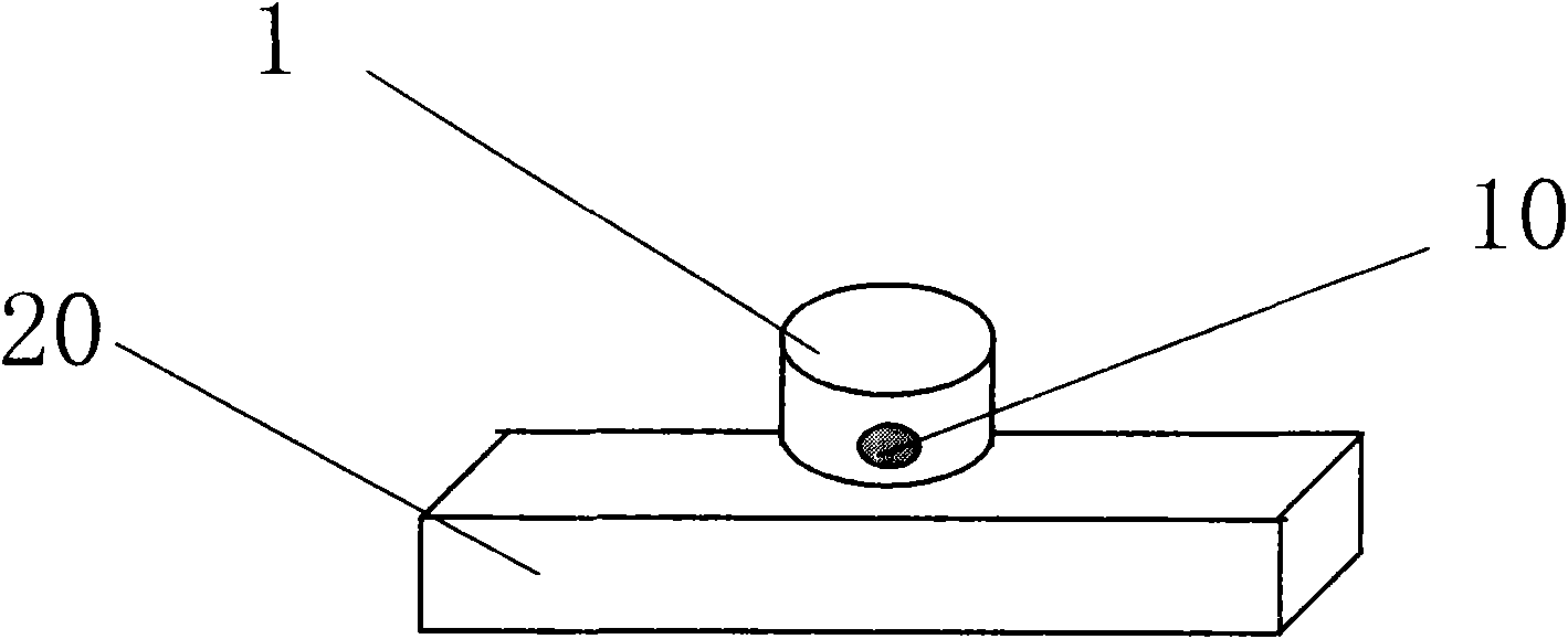
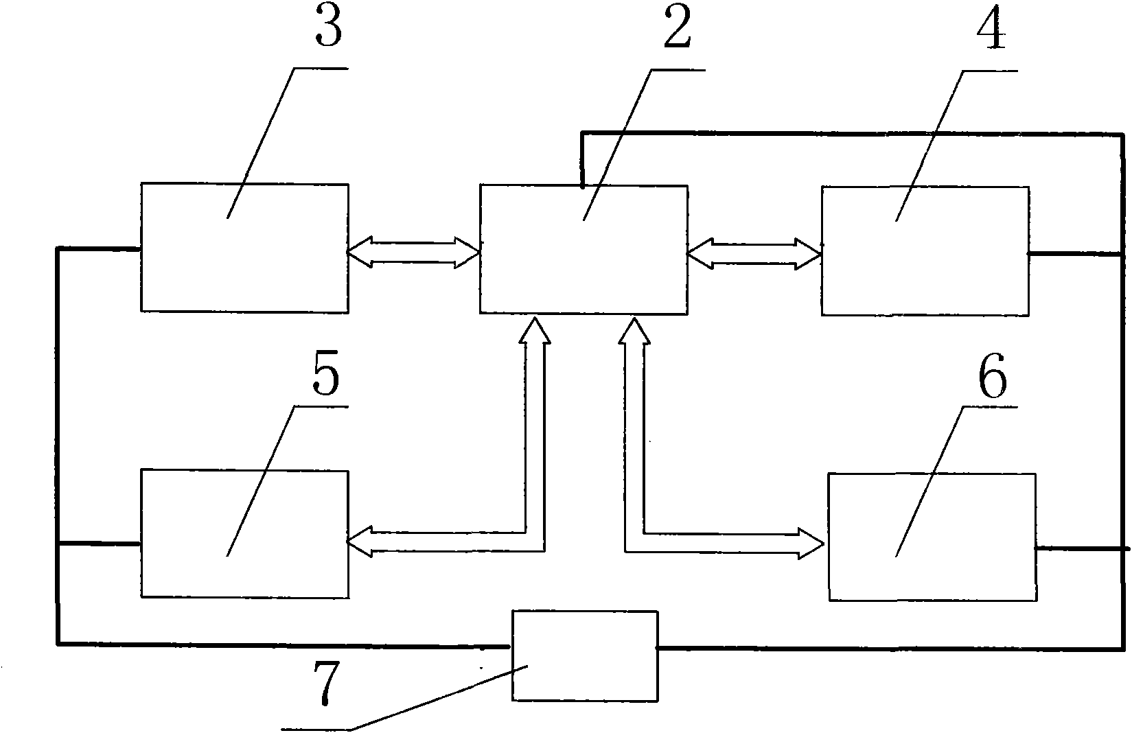
[0030] The radio frequency identification monitoring device for valuables consists of two parts, hardware and software, and the hardware part includes a radio frequency electronic tag 10 and a monitor; figure 1 As shown, the monitor includes a box body 20 and a control circuit board installed in the box body 20, the top of the box body 20 is set as a panel, and an induction antenna is installed in the box body 20 under the panel, and valuables are placed on the panel Item 1; the radio frequency electronic tag 10 is a finished product, which should be embedded in the bottom of the valuable item 1, and the valuable item 1 should be placed within 10cm from the induction antenna under the panel, that is, within the effective monitoring range of the monitor; the control circuit board includes an embedded Processor 2, data reading circuit 3, data storage and communication circuit 4, clock circuit 5, sound and light alarm 6 and power supply 7 and other six parts.

[0031] Such as f...

Embodiment 2

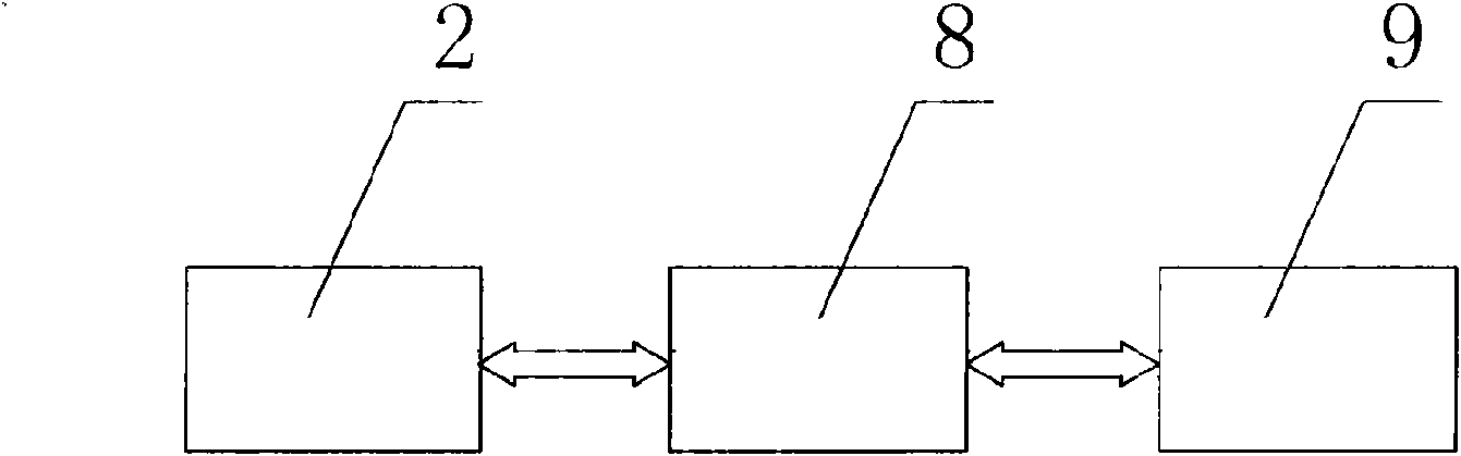
[0038] The second embodiment is basically the same as the first embodiment, except that ten radio frequency electronic tags 10 are installed on the bottom of ten kinds of valuables, and the data reading circuit of the monitor consists of ten coil antennas 9 and ten readings. The module 8 forms ten loops with the same structure, that is, the induction antenna 9 is connected to the input end of the reading module 8 through a wire, and the output end of the reading module 8 is connected to the data input and output ports of the embedded processor 2 .


PUM


Abstract

The invention relates to a radio frequency identification monitoring device for valuables, which comprises a hardware part and a software part, wherein the hardware part comprises a radio frequency electronic label and a monitor, the monitor is internally provided with an induction antenna, an embedded processor, a data identifying and reading circuit, a data storage and communication circuit, a clock circuit, an audible-visual alarm and a power control circuit board. The radio frequency electronic label is embedded at the bottom of the valuables, the induction antenna is connected to the embedded processor through an identifying and reading module, and the data storage and communication circuit, the clock circuit and the audible-visual alarm are respectively connected to the embedded processor through data address lines. The device has scientific, reasonable and creative design, strong practicability and wide application range. The device has the advantages that due to the adoption of the radio frequency identification technology, the automatic identification and the real-time monitoring management to the valuables can be realized, an alarm is made in time to illegal taking or state abnormality to prevent the valuables from being stolen and lost, therefore, the device has good application prospect.

Description

technical field [0001] The invention relates to an automatic identification monitor, in particular to an automatic monitoring device which uses radio frequency identification technology to automatically identify and monitor valuables stored in a fixed location. Background technique [0002] At present, most of the monitoring and management of valuables is to use infrared rays or surveillance video to collect real-time data on the site conditions, and use security personnel to monitor in real time in different places to find abnormalities. Therefore, with this monitoring method, due to human negligence, it is inevitable that when valuables are abnormal or stolen, sometimes they cannot be found in time, and of course it is impossible to upload the abnormal information to the management and control center in a timely and accurate manner, so that timely file and take appropriate action immediately. In addition, this monitoring method cannot realize automatic and effective compu...

Claims


Application Information

Patent Timeline
Patent Type & Authority Applications(China)
IPC IPC(8): G06K17/00G06K7/00G08B13/22
Inventor 马秀丽马晓明李莹
Owner SHENYANG LIGONG UNIV
Why Eureka
Try Eureka