Permanent magnetic independent generator

A generator and permanent magnet technology, applied to electrical components, electromechanical devices, synchronous machine parts, etc., can solve problems such as limited social benefits and restrictions on mass production

Inactive Publication Date: 2009-11-11
张成华
View PDF2 Cites 7 Cited by
  • Summary
  • Abstract
  • Description
  • Claims
  • Application Information

AI Technical Summary

Problems solved by technology

But precisely because of its small size, it also seriously restricts its large-scale production, and its social benefits are also very limited.

Method used


Image

  • Permanent magnetic independent generator
  • Permanent magnetic independent generator
  • Permanent magnetic independent generator

Examples


Embodiment 1

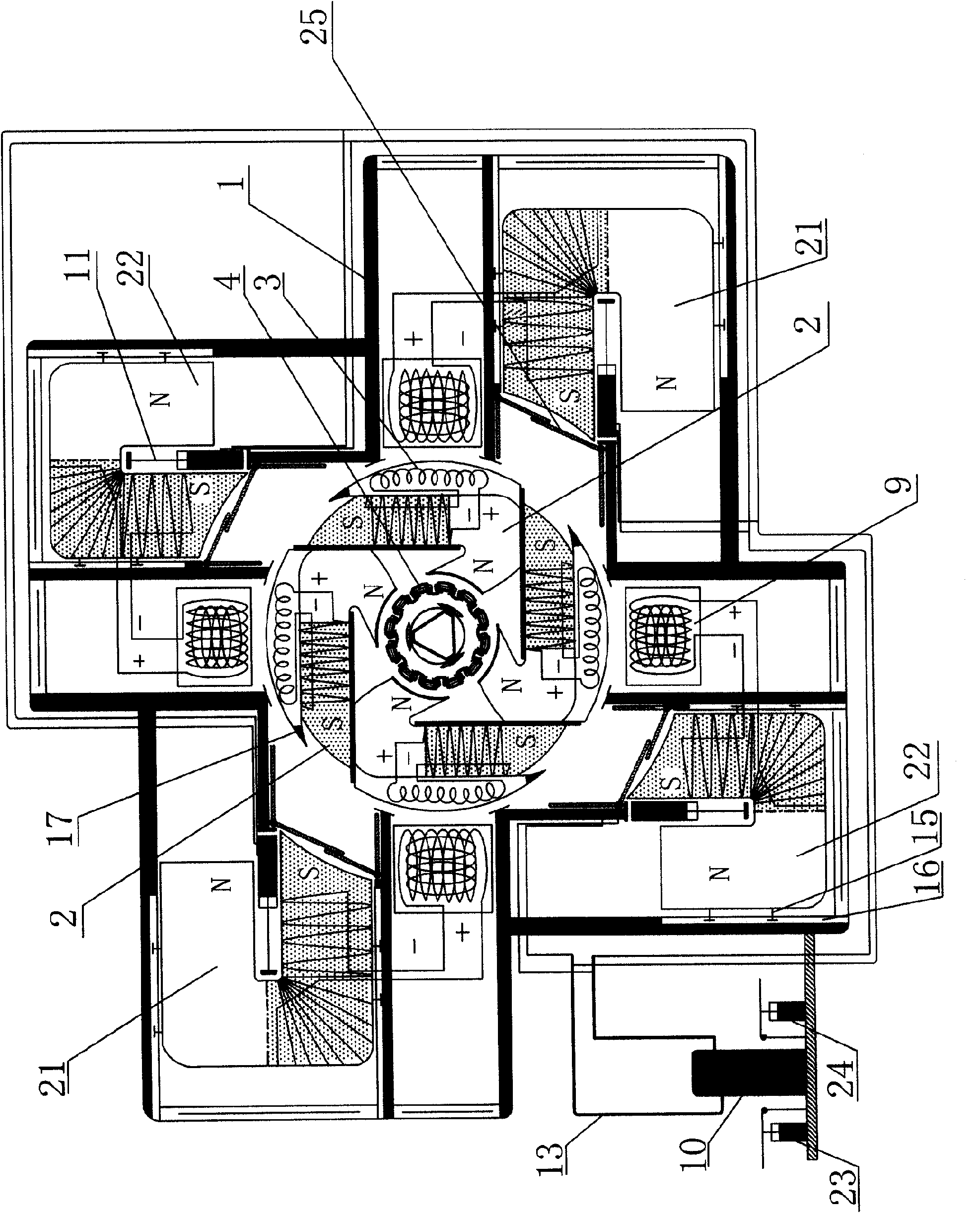
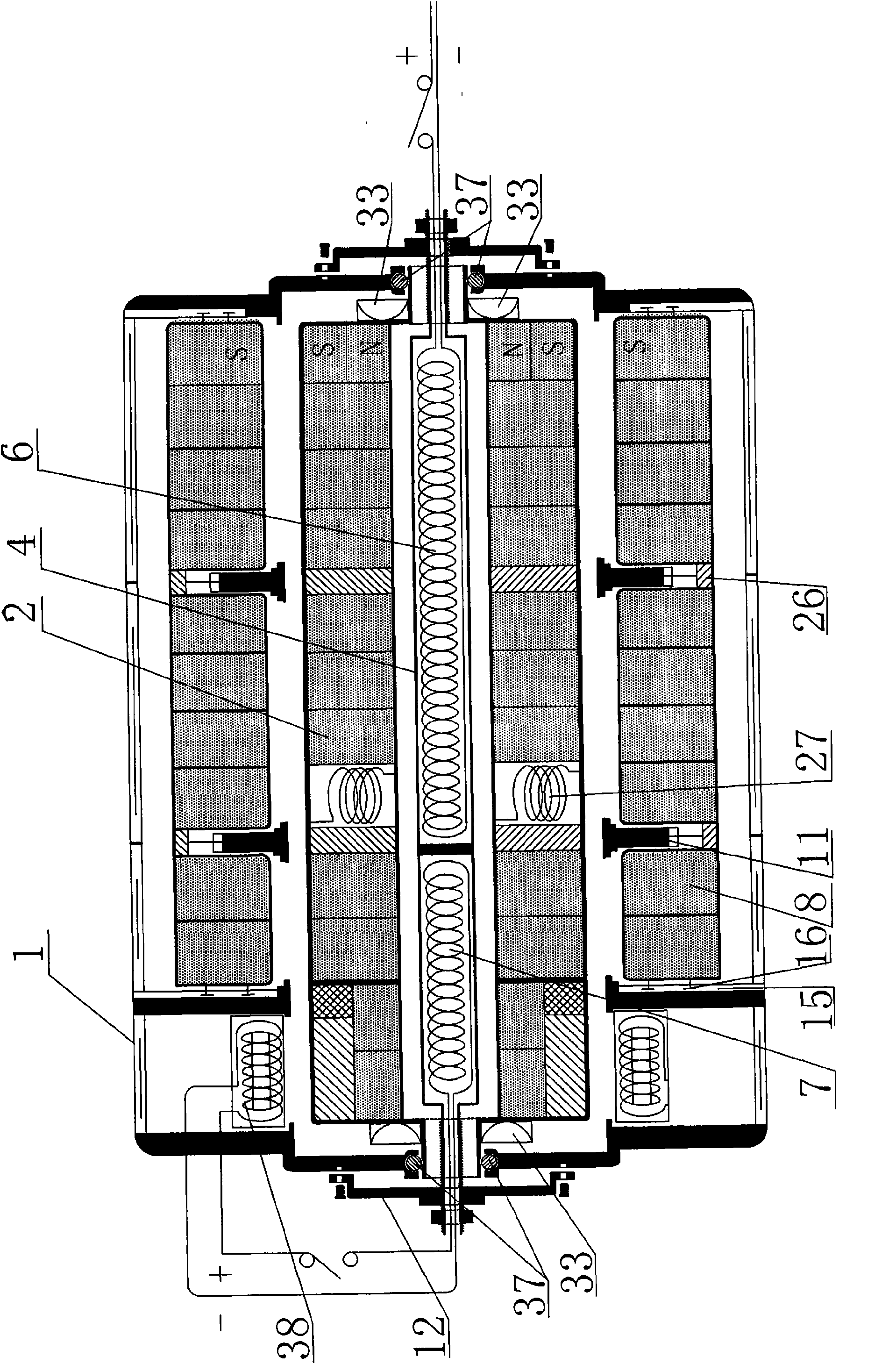
[0070] A permanent magnet independent generator, such as figure 1 , figure 2 , Image 6 and Figure 10 Shown, comprise housing 1, rotor 34 and stator 4, stator 4 is arranged on the center of generator, rotor 34 is arranged on the periphery of stator 4, rotor 34 periphery is provided with mover 35, mover 35 is made up of several mover magnets 8 and The mover magnet coil 9 is composed of the rotor 34. The rotor 34 is composed of several rotor magnets 2 and the rotor magnet coil 3. The mover magnet chute 16 is arranged on the inner wall of the housing 1, and the mover magnet 8 is set in the mover magnet fixing sleeve. Inside 14, a sliding pin 15 is arranged on the outer side of the moving magnet fixing sleeve 14, and the sliding pin 15 is embedded in the moving magnet chute 16 so that the sliding pin 15 and the moving magnet chute 16 form a sliding connection, and the groove of the moving magnet 8 is connected through the Part 26 is connected with hydraulic sub-top 11, and hy...

Embodiment 2

[0072] like figure 1 , figure 2 , Figure 8 , Figure 9 , Figure 10 , Figure 11 and Figure 15 As shown, the mover 35 is arranged in the sliding groove in the generator casing 1, and four rows of mover magnets 8 and mover solid magnetic coils 9 are arranged around the circumference, and each row of movers in the longitudinal direction is composed of twelve single U-shaped mover magnets 8 and correspondingly configured mover solid-magnet coils 9. This is a better quantity setting. The mover row is composed of four single U-shaped mover magnets 8 and the corresponding mover fixed-magnet coils 9 in a circle. Each row When the mover is packaged as a whole, two connectors 26 that can connect the hydraulic sub-jack 31 of the hydraulic sub-top 11 are respectively provided at the concave U-shaped bottom of the U-shaped mover magnet 8, and each row of movers 35 is in the U-shaped The bottom is divided longitudinally into two hydraulic sub-tops 11, and the hydraulic sub-tops ar...

Embodiment 3

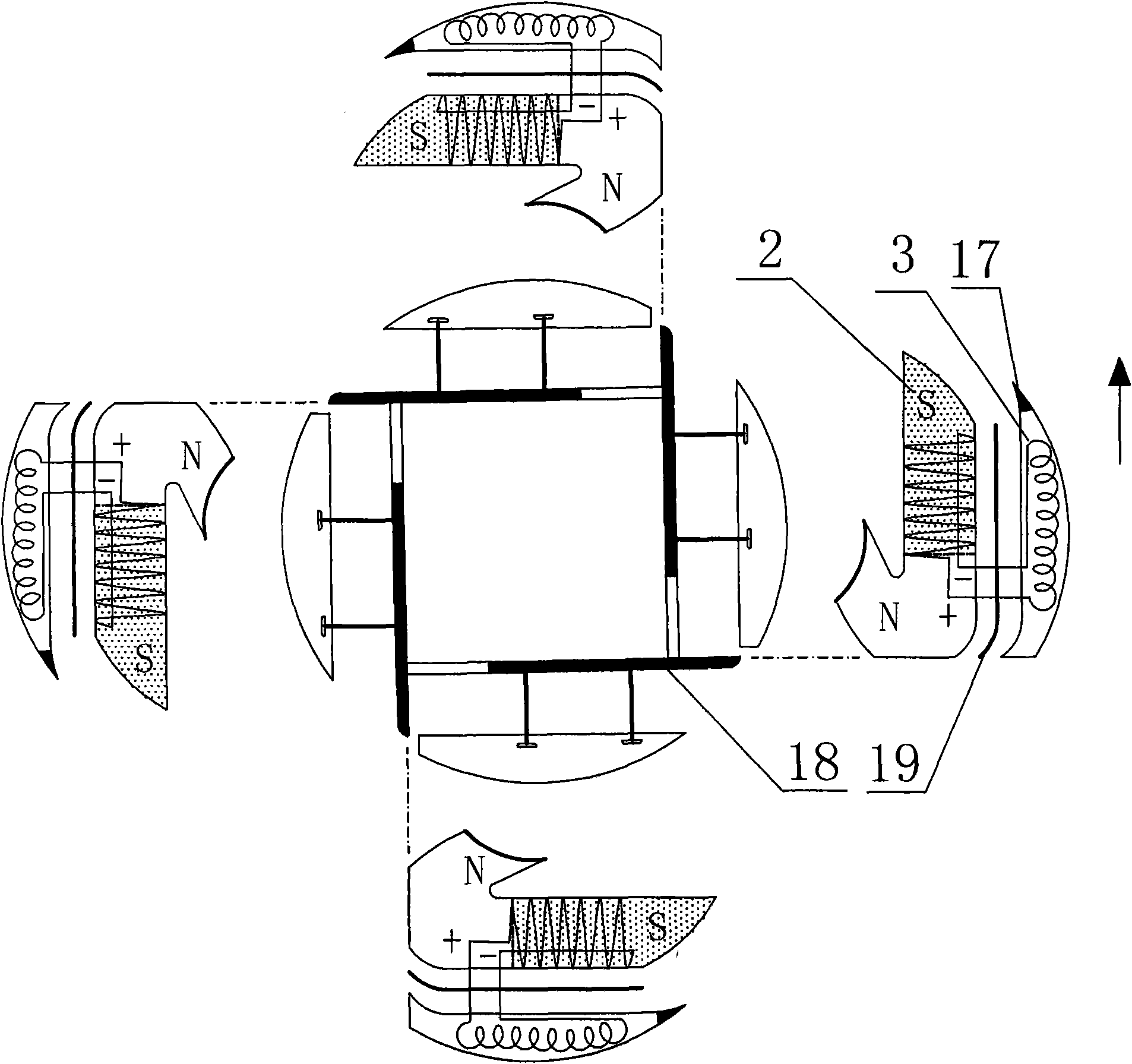
[0074] like figure 1 , figure 2 , image 3 , Figure 14 and Figure 15As shown, the rotor 34 is arranged in the middle layer of the generator, and its rotor 34 is longitudinally provided with twelve peripheral rotors, which is a preferred number setting (in actual use and manufacture, the number of longitudinal peripheral rotors can be increased or increased according to the needs of actual conditions. reduced, but the same as the number of individual movers arranged in the longitudinal direction of the movers), each rotor is composed of four single rotor magnets 2 and four correspondingly configured rotor solid magnetic coils 3, wherein the S pole of one rotor magnet 2 The side surface is close to the outer surface of the N pole of the previous rotor magnet 2, and the rotor solid magnetic coil 3 is arranged close to the outer side of the S pole. These four form a circle to form a tubular circumferential rotor. The purpose is to make the tubular circumferential rotor form...


PUM


Abstract

A permanent magnetic independent generator comprises a shell, a rotor and a stator, wherein the stator is arranged at the center of the permanent magnetic independent generator; the rotor is arranged at the periphery of the stator, the periphery of the rotor is provided with an active cell, the active cell is formed by a plurality of active cell magnets and active cell fixing magnetic coils, and the rotor is formed by a plurality of rotor magnets and rotor fixing magnetic coils; the inner wall of the shell is provided with an active cell magnet sliding chute, the active cell magnet is sleeved into an active cell magnet fixing sleeve, the outer side of the active cell magnet fixing sleeve is provided with a sliding pin which is connected with the active cell magnet sliding chute in a sliding way, a groove of the active cell magnet is internally connected with a hydraulic jack through a connecting piece, the hydraulic jack is connected with a hydraulic total pump, a hydraulic starting device and a hydraulic arresting device through a hydraulic pipeline, and the position on the inner lateral wall of the shell, near the front end of the S pole of the active cell magnet, is provided with an elastic magnet isolating subassembly. The invention converts the repulsive force of same magnetic poles into rotary force so that the rotor rotates and then a stator coil generates current, thereby the purpose of power generation is achieved; in addition, the invention has the advantages of energy saving and good effect.

Description

technical field [0001] The present invention relates to a generator, in particular to a permanent magnet independent generator which drives the rotor to rotate by repelling the rotor magnet arranged on the outer periphery of the rotor with the same sex as the rotor magnet, so that the coil winding in the stator cuts the magnetic field lines to generate current. It belongs to the technical field of magnetic power generation. Background technique [0002] The birth of generators has brought great contributions to human progress and civilization. Airplanes, ships, automobiles, lighting and all working and living environments that are closely related to electricity do not need the protection of electricity all the time. However, the source of electricity is people As we all know, other energy needs to be transformed through a series of mechanical movements to obtain electricity. The easiest way is to make the wire cut the magnetic force line to generate current, but to make the ...

Claims


Application Information

Patent Timeline
Patent Type & Authority Applications(China)
IPC IPC(8): H02K53/00H02K16/00
CPCH02K16/00H02K53/00H02K21/04
Inventor 张成华
Owner 张成华
Why Eureka
Try Eureka