
Apparatus for rivetting

A riveting device and rivet technology, applied to rivets, connecting components, threaded fasteners, etc., can solve the problems of taking more time, increasing energy loss, and increasing cooling time, so as to improve the quality of riveting operations, increase productivity, and improve The effect of energy efficiency

Active Publication Date: 2009-11-11
GUNYANG ITT
View PDF0 Cites 18 Cited by
  • Summary
  • Abstract
  • Description
  • Claims
  • Application Information

AI Technical Summary

Problems solved by technology

[0015] However, the size of the enclosure surrounding the forming tool 34 and the heater 32 in this device cannot exceed a certain limit, the heater located inside the enclosure is limited in size which limits the amount of hot air that can heat one end of the rivet 1, thus melting the end of the rivet takes more time
In particular, since hot air is supplied only to the outer peripheral surface of one end of the rivet 1, it takes a long time to melt to the inner side of the end of the rivet 1.
Moreover, since the cooling time of the forming tool 34 and the heater 32 need to be cooled simultaneously when the rivet 1 is cooled, the forming tool 34 and the heater 32 need to be heated simultaneously when the rivet 1 is heated. operating time and increased energy loss

Method used


Image

  • Apparatus for rivetting
  • Apparatus for rivetting
  • Apparatus for rivetting

Examples


Embodiment Construction

[0044] The preferred embodiments of the riveting device of the present invention will be further described below in conjunction with the accompanying drawings.

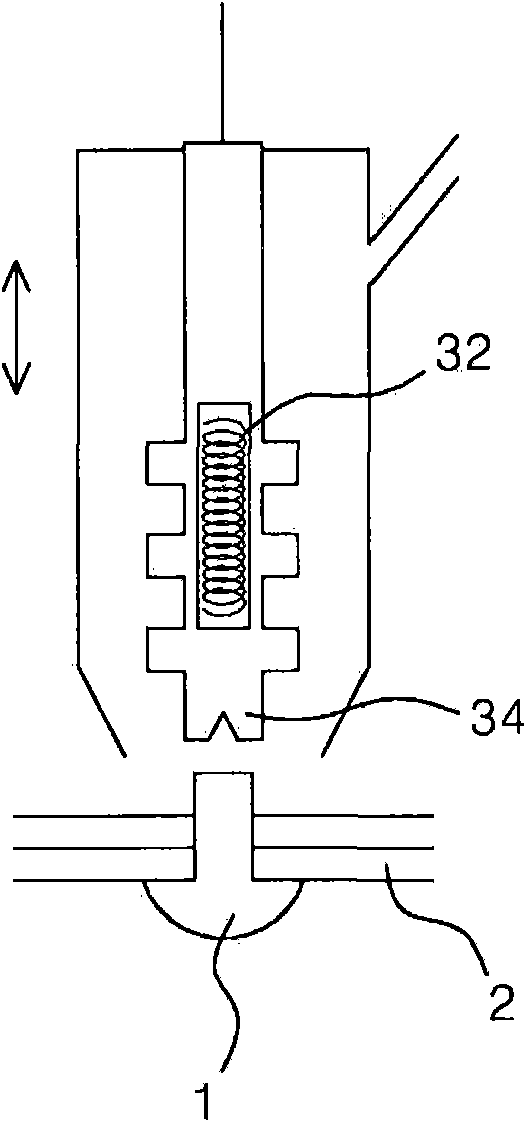
[0045] Figure 4 It is a cross-sectional view of the forming tool and other parts of the embodiment of the riveting device of the present invention.

[0046] Such as Figure 4 As shown, the riveting device of the present invention mainly includes a hot air pipe 200 , a connecting pipe 100 , a forming tool 300 , a moving unit and a guide 500 .

[0047] First, the hot air pipe 200 will be described. The above-mentioned hot air pipe 200 is in the shape of a hollow tube, which can provide a passage for the hot air.

[0048] The connecting pipe 100 is also in the shape of a hollow pipe, which is combined with the lower end of the hot air pipe 200 to provide a path for the hot air flowing through the hot air pipe 200 .

[0049] In order to improve heat transfer efficiency, the connecting pipe 100 is made of a metal materi...


PUM


Abstract

A riveting apparatus includes a hot air pipe; a connection pipe coupled to the hot air pipe; a forming tool having a configuration in which peripheral and center portions project downward and portions existing therebetween are curved upward, defined with discharge holes which extend in axial and radial directions, and coupled to a lower end of the connection pipe so that hot air having passed through the connection pipe can be discharged through the discharge holes to heat an end of a rivet to thereby allow the forming tool to form the end of the rivet into the shape of a head; a moving unit coupled to the hot air pipe or the connection pipe to move the forming tool upward and downward; and a guide surrounding the forming tool so that hot air discharged through the discharge holes can be directed toward the end of the rivet.

Description

technical field [0001] The present invention relates to a riveting device which melts the tip of the rivet by discharging hot air through the discharge holes of the forming tool in the axial and radial directions, and then drives the forming tool down to apply pressure to the tip of the rivet and make it Formed into a head shape, and cooling air is supplied to the forming tool and the connecting pipe connected to the upper side of the forming tool to lower the temperature of the forming tool, thereby cooling the tip of the rivet formed into a head shape and in contact with the forming tool . Background technique [0002] Like automotive interior materials, when multiple plastic panels are combined in a laminated manner, a through hole is usually processed on the edge of the panel, and a rivet with one end shaped like a head is inserted into the through hole, and then Shape the other end of the aforementioned rivet into a head shape. [0003] Since the above-mentioned rivet...

Claims


Application Information

Patent Timeline
Patent Type & Authority Applications(China)
IPC IPC(8): F16B19/12
CPCB29C65/72F16B19/12B29C66/81431B29C65/30B29C66/8322B29C66/1122B29C66/81423B29C65/602B29C66/43B29C66/81812B21J15/36B29C66/348B29C66/8227B29C66/3494B21J5/00B21J15/08B29C65/26B29C65/10B29C66/8242B29C65/18B29C65/601B29C66/81811B29C66/81429B29C66/0342B29C66/21Y10T29/53774B29C65/00F16B19/00
Inventor 金择铉
Owner GUNYANG ITT
Features
  • Generate Ideas
  • Intellectual Property
  • Life Sciences
  • Materials
  • Tech Scout
  • Unparalleled Data Quality
  • Higher Quality Content
  • 60% Fewer Hallucinations
Learn More